Removing the Mainboard
1.See “Removing the Side Panel” on page 30.
2.See “Removing the Front Bezel” on page 31.
3.See “Removing the Heat Sink Fan Assembly” on page 32.
4.See “Removing the Processor” on page 33.
5.See “Removing the Optical Drive” on page 34.
6.See “Removing the Hard Disk Drive” on page 37.
7.See “Removing the Memory Modules” on page 40.
8.See “Removing the TV Tuner Card” on page 41.
9.See “Removing the VGA Card” on page 42.
10.See “Removing the Front I/O and Card Reader Boards” on page 43.
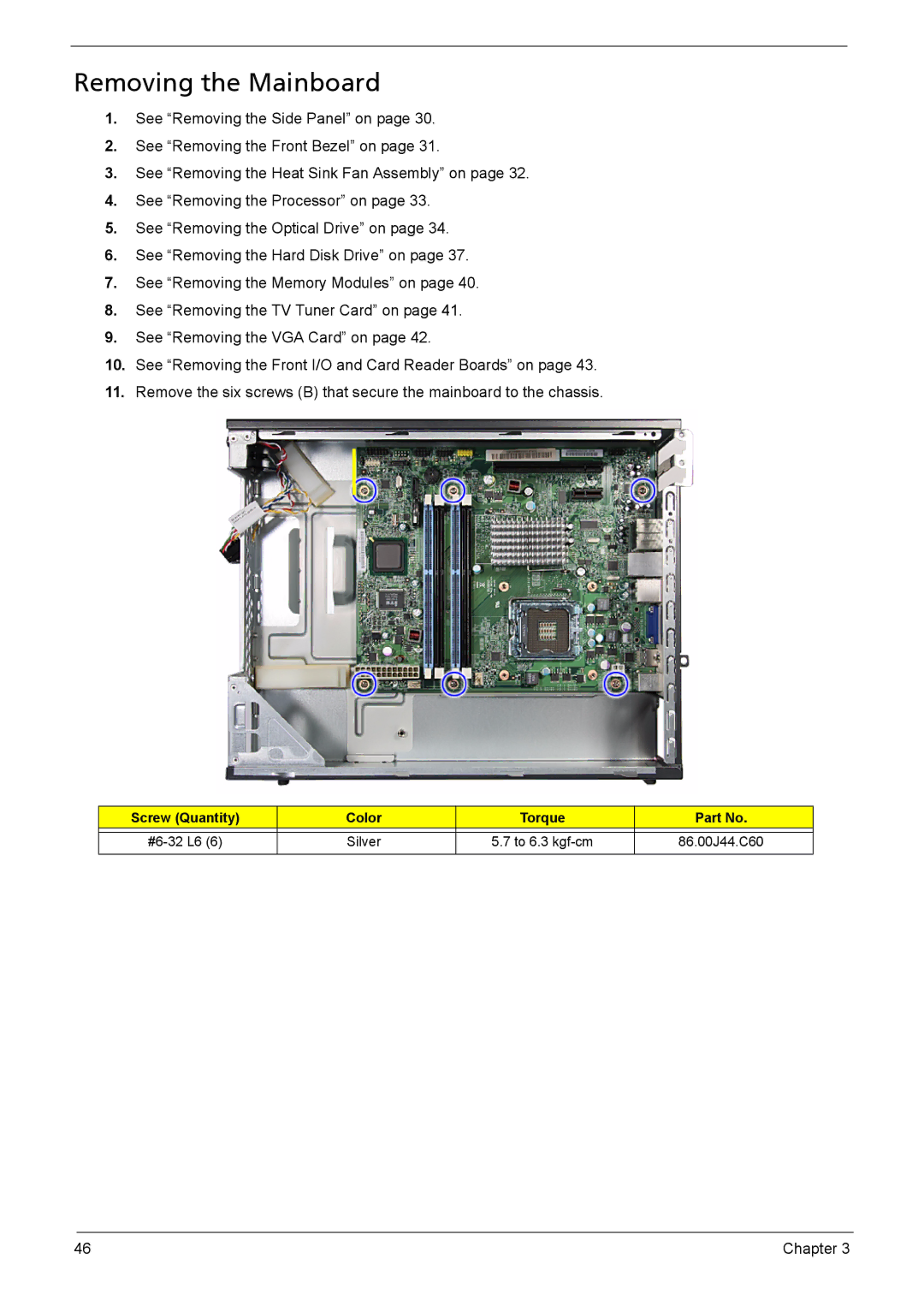
11.Remove the six screws (B) that secure the mainboard to the chassis.
Screw (Quantity) | Color | Torque | Part No. |
|
|
|
|
Silver | 5.7 to 6.3 | 86.00J44.C60 | |
|
|
|
|
46 | Chapter 3 |