Liebert DS
Page
Table of Contents
Electrical Connections
Maintenance
Piping
108
Compressor Replacement
Hvac Maintenance Checklist
Figures
Page
Page
Tables
Viii
Important Safety Instructions
Page
Downflow model component locations
Liebert DS Components and Nomenclature
Upflow model component locations
= Dual-Cooling Water/Glycol Three-stage Compressor
U a
Glycool
Cooling Configurations
PRE-INSTALLATION Guidelines
Room Preparation
Air Distribution-Downflow Units
Air Distribution-Upflow Units
Upflow ducting configurations
Operating Conditions
Connections and System Setup
Shipping dimensions-domestic and export, inches mm
Liebert DS Dimensions and Weights
Shipping weights-approximate, kg
028/035/042 053/070/077
Model No 028, 035
Approximate
Dry Weight, lb kg Approximate Model No 028, 035
Top View
Front View
DPN000894
Dry Weight lb. kg Approximate
51mm
GLYCOOL/Dual-Cool
Front View
Dry Weight, lb kg Approximate Model 053 070 077
070 077
Dry Weight, lb kg Approximate Model No
TOP View
Compressor Dry Weight, lb kg, Approximate Type Model 053
Dry Weight, lb kg approximate Compressor Type Model
Top View
Front View
Dry Weight, lb kg approximate Compressor Type Model 105
Dry Weight, lb kg
Model No 028-042
Compressor Type Model
Dry Weight, lb kg approximate
Alternate Refrigerant Piping Entrance
Model No 053, 070
Top View
Weights-upflow, air-cooled, 105kW 30 ton, all
Dry Weight, Approximate, lb kg
Model 105
Compressor GLYCOOL/Dual-Cool
Height, in. mm Turning Vane
Dimensions, in. mm Model
Floor stand dimensions-downflow, 53-77kW 15-22 ton models
Floor stand dimensions-downflow, 105kW 30 ton models
Models Blower Supply
Dimensions for upflow, 28-42kW 8-12 ton
Dimensions, in. mm Models Blower Supply
Blower outlet and deck dimensions-upflow, 53-77kW 15-22 ton
Dimensions, in. mm Models Blower
Blower outlet and deck dimensions-upflow 105kW 30ton
Dimensions, in mm Compressor Type # Filters
Rear return filter box dimensions
Left Side Views Right Side Views Check One
Equipment Inspection and Handling
Packaging Material
Step 181659P1 Rev
Unpacking the Unit
Step
Removing the Unit from the Skid With a Forklift
Removing Piano Jacks
Moving the unit to its installation location
Rev
Removing Liebert DS from Skid Using Rigging
Lifting Sling Equal Equal Distance Distance
Placing the Unit on a Floor Stand
Semi-Hermetic Compressor Spring Isolation System
Detail a
Liebert Floor Stand front discharge shown
Disassembly-Downflow Units
Required Equipment
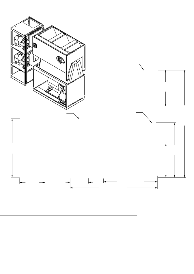
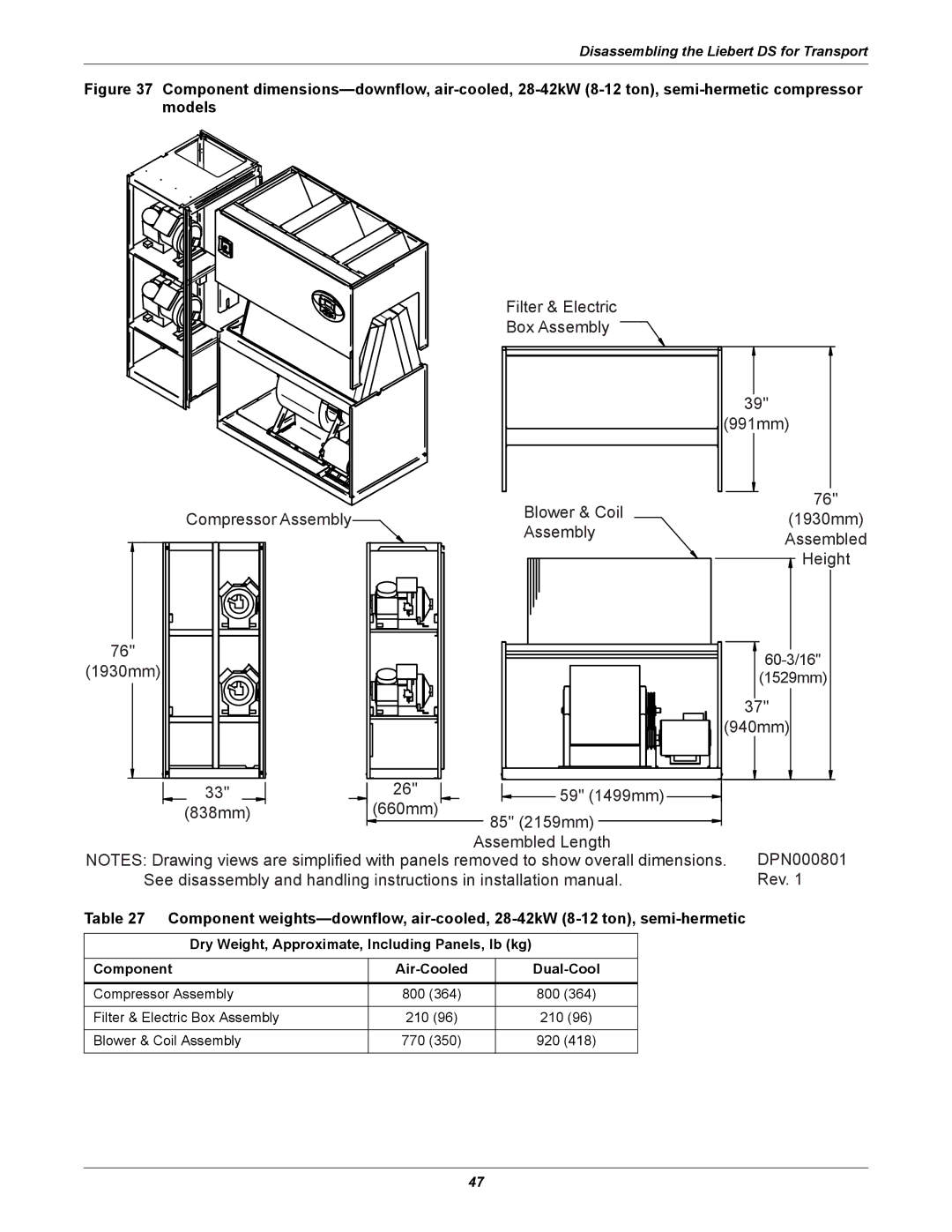
Disassembling the Liebert DS for Transport
Reheat-Optional Component
Remove the Filter and Electric Box Assembly
Remove the Compressor Assembly
Reconnecting Piping, Charging and Replacing Panels
Reassembly-Downflow Units
Reassembly Checklist
Filter & Electric Box Assembly
Filter & Electric Box Assembly
940mm
1930mm
Assembly Assembled Height 1930mm 59-7/16
Filter and Electric Box Assembly
Blower & Coil Assembly
Semi-Hermetic Compressor Scroll Compressor
Component Air Cooled Dual Cool
Dry Weight, lb kg Approximate Includes Panels
Filter & Electric
1510mm
Disassembly-Upflow Units
Remove Blower and Electric Box Assembly
Remove Compressor Assembly
Reassembly-Upflow Unit
2159mm
31-1/4 794mm
85 2159mm Assembled Length
660mm 2083mm 108 2743mm Assembled Length
82 2083mm
Blower & Electric Box Assembly 31-1/4
REV
REV
31-1/4 794mm
Electrical Connections
Downflow LOW Volt Section
Electrical Field Connection Descriptions
Standard Electrical Connections
Optional Electrical Connections
Optional Low Voltage Terminal Package Connections
Fluid Connections
Condensate Piping-Field-Installed
Piping
Gravity Drain
Gravity drain for downflow and upflow units
Condensate Pump
Requirements of Systems Using Water or Glycol
Humidifier Supply Water-Optional Infrared
General Guidelines
Leak Checking of Unit and Field Piping
Refrigeration Piping
Recommended refrigerant line sizes OD copper inches
Piping Guidelines-Air-Cooled Units
Fan Lee-Temp Model Speed Includes receiver
Liquid Line, lb kg
Fan Speed Control Leak Check and Evacuation Procedure
Fan Speed Control Piping
Fan Speed Control Materials Supplied
Fan Speed Charging
Fan speed suction pressure transducer settings
Lee-Temp Leak Check and Evacuation Procedure
Lee-Temp Piping
Lee-Temp Controlled Materials Supplied
Lee-Temp suction pressure transducer settings
Lee-Temp Charging
Lee-Temp Receiver Refrigerant Level
Piping schematic-air-cooled, semi-hermetic compressor models
Piping Schematics
Fan Speed
Lee-Temp
Liebert DS Unit
Customer Heat Rejection
Liebert
Associated piping
Piping schematic-GLYCOOL semi-hermetic compressor models
Liebert
Customer Heat Rejection
Glycool with digital scroll compressor models
DPN000805 Rev
Optional piping schematic for Econ-O-Coil
Point Description Inches mm
Connection Size / Opening
DPN000804
Front of Unit
53kW 15ton / 70 & 77kW 20 & 22ton
DPN000929 Rev
DPN000933
HUM E1 E2 Front of Unit
DPN001015
CGD
TOP View
Top View of Unit
Left Side Section View
Front Section View
Point Description In. mm
53kW 15 ton/70 & 77kW 20 & 22 ton
Left Side Section View of Unit
53kW 15 tons/70 & 77kW 20 & 22 ton
Left Side Section View
Front Section View
Left Side Section View
Point Description Connection Size / Opening
Piping data-upflow, air-cooled 105kW 30 ton, all
Point Description Inches mm Opening, inches mm
Connection Size
Moving and Placing Equipment
Checklist for Completed Installation
Electrical
Other
108
109
Commissioning Procedure With Panels On
Filters
Maintenance
Filter quantities, downflow units
Filter quantities, upflow units
Filter Replacement Procedure-Downflow Units
Filter Replacement Procedure-Upflow Units
Blower Drive System
Upflow Motor Access
Belt Installation and Tensioning
Belt Removal
Blower Bearing Replacement
Blower Bearing Maintenance
Blower Bearing Inspection
Blower Motor
Humidifier
Correct orientation of float switch
Changing Humidifier Lamps
Condensate Drain and Condensate Pump Systems
Condensate Drain
Infrared Bulbs
Air-Cooled Condenser and Drycoolers
Reheat-Electric Reheat Three-Stage and SCR
Compressor
Facility Fluid and Piping Maintenance
Compressor Replacement
Adjustment-Johnson Controls/Penn Johnson Valves
Cleaning Instructions
Paradenser-Water-Cooled Condenser
Water/Glycol Control Valves
Adjustment
Testing Function of Valve
Location
12.11.2Motor Ball Valve-Digital Scroll Compressors
Aquastat settings-two-fan through four-fan drycoolers
12.11.3Drycooler Settings
Aquastat settings-six-fan drycoolers
Aquastat settings-eight-fan drycoolers
Hvac Maintenance Checklist
Water-Cooled Condensers
Refrigeration Piping
Compressor Section
Electrical Panel
Glycol Pump
Air-Cooled Condenser / Drycooler
Page
Iti
Ne t
Ti n
That