Manuals
/
Active Thermal Management
/
Photography
/
Security Camera
Active Thermal Management
UVS-7111
manual
Audio/Video Output, LAN Socket, External alert bus DI/DO
Models:
UVS-7111
1
7
68
68
Download
68 pages
29.47 Kb
4
5
6
7
8
9
10
11
Install
Attachment A External Alarm
Wireless networking mode
Resets all parameters
Access to Camera
RS-485 connector
Backup Data backup
Camera Settings
Wiring of the product DC Power
SSID Service Set Identifier
Page 7
Image 7
Page 6
Page 8
Page 7
Image 7
Page 6
Page 8
Contents
Page
Network cable network setting page
Contents
UVS-7111 Users Manual
Content
2. 12V DC power cable
Package Contents
5. Warranty card/certificate
Packaging Contents
System Requirements
System Requirements
UVS-7111/7111P/7111W Video Server
Introduction
Features and Advantages
Introduction / Features and Advantages
System Instructions
Wiring of the product DC Power
System Instructions
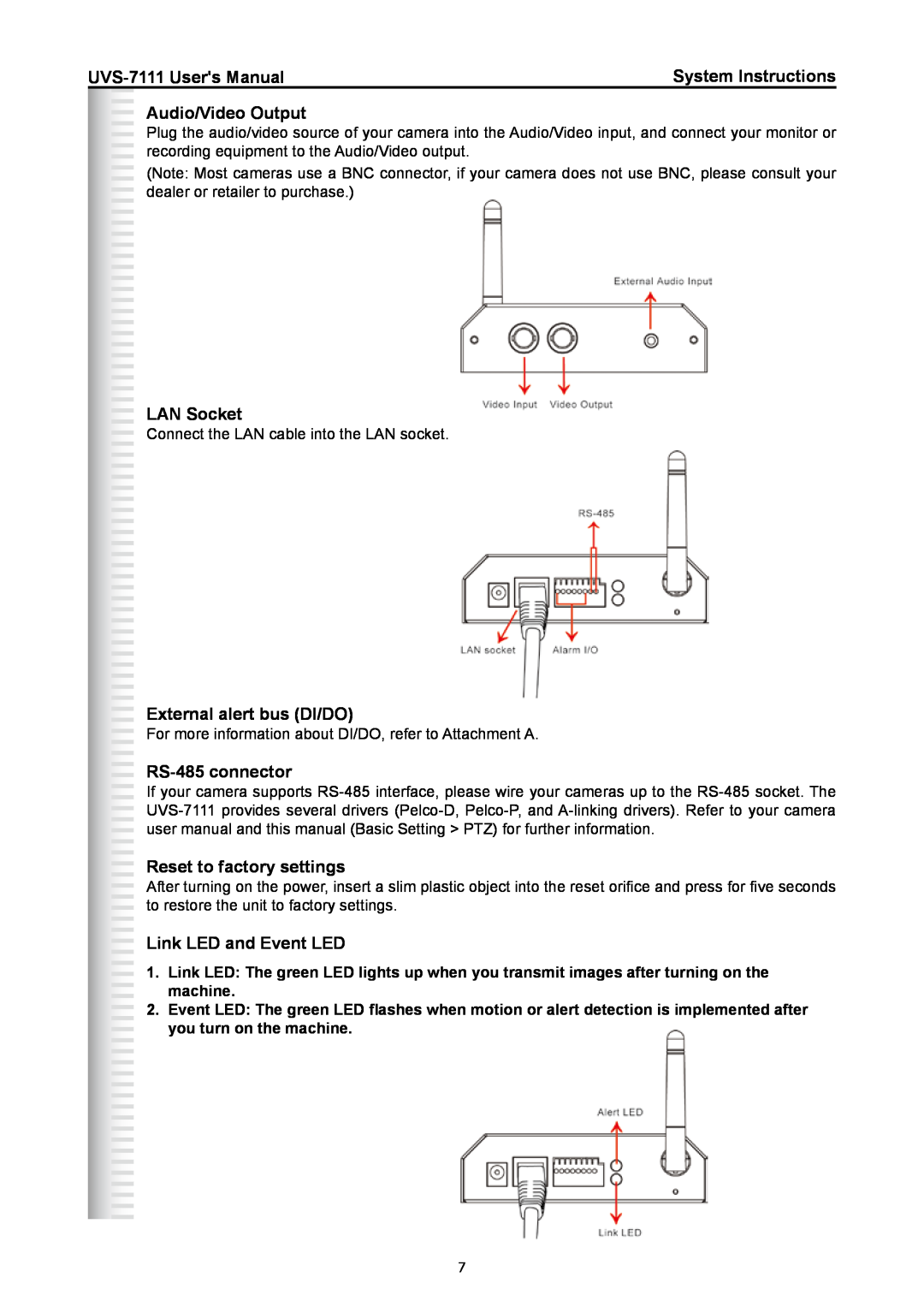
LAN Socket
RS-485 connector
Reset to factory settings
Audio/Video Output
6. Connect to the power source
Hardware Installation
1. Select the installed place
4. Connect to the power source for your camera
2. Find the camera Search
Camera Settings
Camera Settings
1. Start the machine
FINDER software
Camera Setting
5. Confirmation
MAC Factory default network identity of the machine
3. Enter the Virtual Server setting page
Camera Setting from a Router
Camera Setting from a Router
Change the Internet Explorer Setting
Change the Internet Explorer Setting
Steps
1. Open the IE browser and key in the IP address of the product
2. Key in the default username and password
3. Installation of Internet Explorer ad-hoc components
Enter the Main Page
Click Install
4. The security warning screen appears. Click Install
Camera main page and image
Descriptions
Camera Main Page
Camera Main Page
Control panel
3. Control the camera direction 2. Enter the name of the location
3. Preset presets the rotation points for the camera 16 points
1. Click Set to enter the Preset Setting screen
4. Click Update to exit 5. Select the number you need
5. AutoPan enables/disables AutoPan
4. Tour enables/disables the tour mode of the camera
The rotation points of the camera must be set up in advance
Enable/ disable the alert message Save function
7. Alert Message enables/disables the alert message display
6. Alert displays alert trigger
Enable/ disable the alert message display Alert message display area
9. Camera Position sets the position for display of the image
8. Language selects a UI language
10. View Size selects the size of the image
Refer to Setting/Basic Setting/Network/Streaming for more information
11. Streaming sets the video stream protocol HTTP is recommended
14. Snapshot executes the snapshot function
13. REC executes the video recording function
17. ANS Automatic Noise Suppression system
16. Audio On/Off turns on/off the pickup function
Basic Setting System System Info
System Settings
Basic Settings
Basic Setting System System info
Ex Nokia N71. Follow these steps to set up your 3G viewing function
Basic Setting Video/Image
Basic Setting Video Image Video Image
Basic Setting Video / Image Video Image 3GPP
11. Video stream screen
4. Enter the link name 6. Select OK to save the setting
7. Select this stream name to proceed with linking 9. Connecting
8. Select “Yes” to connect 10. Loading the image
Basic Setting Video / Image Video Image Video Resolution
Basic Setting Video / Image Video Image Video Format
The product offers 4 image resolutions PAL/NTSC 1. D1 704x576 2. VGA
Select a video quality
Basic Setting Video / Image Video Image Frame per Second FPS
Basic Setting Video / Image Video Image Video Quality
Select a FPS
Basic Setting Video Image OSD Display Color
Basic Setting Video Image OSD
Basic Setting Video Image OSD Display Mode
Basic Setting Video Image OSD Display Text
Basic Setting Audio Audio sound setting
Basic Setting Audio Sound
Basic Setting Audio Audio Audio Raw Format
Basic Setting PTZ PTZ
Basic Setting PTZ
Basic Setting PTZ PTZ PTZ camera Port Setting
Basic Setting PTZ Serial Port Setting Data bits
Basic Setting PTZ PTZ Driver Manager
Basic Setting PTZ PTZ Driver Upload
Basic Setting PTZ Serial Port Setting
Basic Setting PTZ Serial Port Setting Parity
Basic Setting PTZ Serial Port Setting Stop bits
your cameras for the accurate figure
Basic Setting User User List access privilege list
Basic Setting UserUser
Basic Setting User User Setting privilege setting
Other settings
Basic Setting Network Network setting
Basic Setting Network Network cable network setting page
DHCP setting
Wireless networking mode
Basic Setting Network Wireless wireless network setting page
Basic Setting Network Wireless Wireless
Wireless network setting page
2. AdHoc Point-to-point networking mode
Mode Selection of the wireless networking mode
Authentication Type Network authentication type
1. Infrastructure Infrastructure networking mode
WEP Encryption WEP encryption function
SSID Service Set Identifier
Enter the name of the base station AP to which you want to connect
0~9, a~f, A~F
Encoding
ASCII
Available characters
Selection
Streaming port setting
Basic Setting Network Streaming steaming setting
1. HTTP 2. RTSP 3. RTP
Basic Setting Network PPPoE PPPoE
Basic Setting Network PPPoE dial-up networking setting
Basic Setting Network PPPoE PPPoE Information
Item Description
Basic Setting Network DDNS Dynamic Domain Name Server Setting
To activate the UPnP function in Windows OS
Basic Setting Network UPnP Universal Plug and Play
Basic Setting Network UPnP UPnP Device
Basic Setting Network UPnP UPnP Traversal
1. Open My Network Places
3. View the connection device using My Network Places
2. Click Exceptions 3. Check UPnP Configuration
2. Open Windows firewall option
Basic Setting Network SMTP Server mail server setting
Options
Basic Setting Network Samba
Samba setting
IP address change notice
Basic Setting Network Notification Of IP Address Change
Notification setting
Basic Setting Date/Time Time Setting date/time setting
Basic Setting Date/Time date/time setting
Basic Setting Date/Time Server Time the date/time of the server
Basic Setting Date/Time PC Time the date/time of your PC
Basic Setting IP Filter Filter IP Address Overview of the set IPs
Basic Setting IP Filter
Basic Setting IP Filter General
IP Filtering enables/disables the IP filter
Application Setting Event event trigger setting page
Application Setting
Application Setting Event Event List trigger event setting
Note You can only set one trigger event once
Basic Setting
Add Event Add Event setting page
Options
Trigger mail Sending mail
Application Setting Event Trigger manual test of trigger response
Trigger Alarm output Alarm output
Trigger LED LED indicator display
setting for uploading trigger event file to the server
Application Setting Event Event Servers
UVS-7111 Users ManualApplication Setting
Important! Read Carefully
Application Setting Motion Detection
Application Setting Firmware upgrade
Application Setting
4. Click
Resets all parameters
Application Setting Factory Default
Factory Default Reset to factory default
Resets all parameters, except the IP parameters
File backup
Backup Data backup
Restore backup parameters
Back all parameters
You can enable this function for the camera to reboot automatically
Application Setting Reboot
Alarm Input #1/2 K. Ground
Attachment A External Alarm
Attachment A External Alarm
Alarm Input #1 A. Max 24VDC, 12mA
External Alarm I/O Circuit Diagram
Attachment C Troubleshooting and FAQs
may bring about damage to the camera or product fatal electric shock
Average range of Data Sizes
Image Resolution
Attachment B Bandwidth Estimation
Attachment B Bandwidth Estimation
Function
Answer and Solution
Camera Installation
Question
Access to Camera
the current security setting
Others
Top
Page
Image
Contents