Attachment C: Troubleshooting and FAQs | |||
|
|
|
|
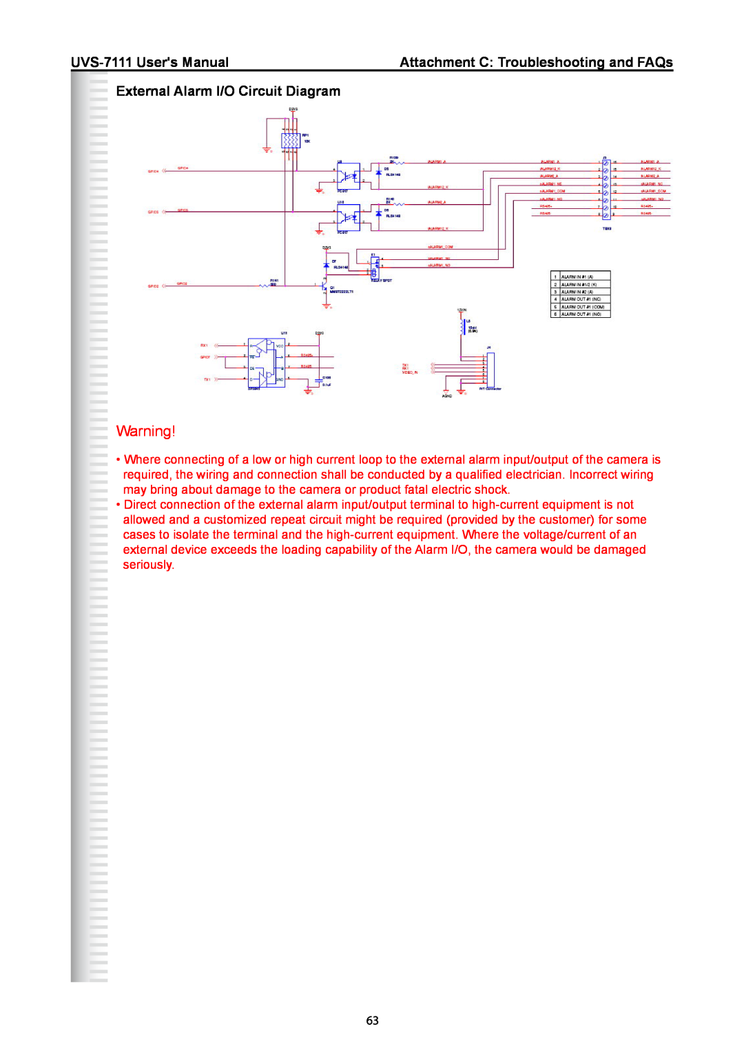
External Alarm I/O Circuit Diagram
Warning!
•Where connecting of a low or high current loop to the external alarm input/output of the camera is required, the wiring and connection shall be conducted by a qualified electrician. Incorrect wiring
may bring about damage to the camera or product fatal electric shock.
• Direct connection of the external alarm input/output terminal to
63