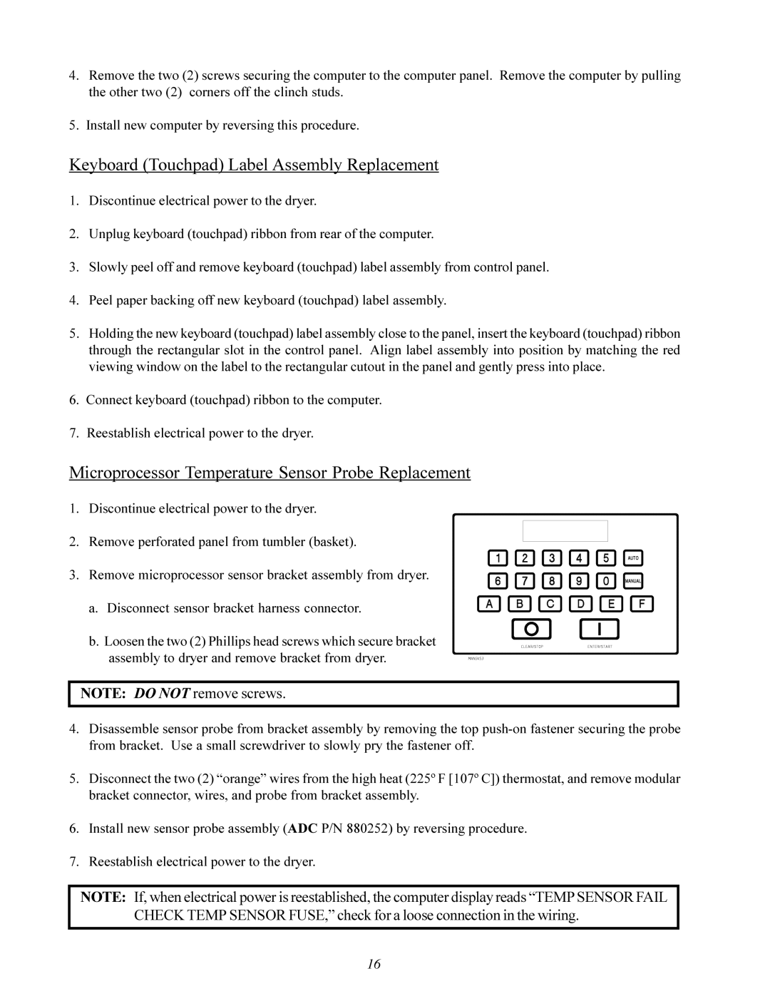
ML-96 specifications
The ADC ML-122 and ML-96 are two advanced communication devices designed for efficient data collection and transmission in various applications. Both models are renowned for their robust performance and user-friendly features, which cater to a diverse range of industries.The ADC ML-122 is a high-performance data logger that excels in multi-channel monitoring. It supports various input types, making it versatile for applications such as environmental monitoring, industrial process control, and research. One of its standout features is its ability to accommodate both analog and digital signals, allowing users to gather a wealth of data from different sources. The device supports a wide temperature range, ensuring reliability in diverse environmental conditions. Moreover, its built-in memory can store extensive data logs, which are easily downloadable for analysis.
On the other hand, the ADC ML-96 is designed primarily for telecommunication and network monitoring. It features advanced signal processing technologies that allow it to analyze and troubleshoot communication lines efficiently. The device is equipped with real-time monitoring capabilities, enabling users to detect issues as they arise, which is crucial in maintaining network integrity. The ML-96's compact design makes it an ideal choice for installation in tight spaces without sacrificing performance.
Both models are built with cutting-edge technologies that enhance their functionality. They integrate wireless communication protocols, such as Wi-Fi and Bluetooth, enabling seamless connectivity to cloud services for data backup and remote access. This feature empowers users to monitor conditions from anywhere, ensuring that critical information is always at hand.
The user interface for both the ML-122 and ML-96 is designed for ease of use. Equipped with a clear display and intuitive controls, users can navigate through settings and view data with minimal training. The devices also offer customizable alerts that notify users of any anomalies, adding an additional layer of security and responsiveness.
In terms of power management, both models utilize energy-efficient components, allowing for extended battery life. This is particularly advantageous in remote sensing applications where power sources may be limited. Furthermore, the ability to integrate with other systems makes these models adaptable to various operational needs.
In conclusion, the ADC ML-122 and ML-96 stand out in their respective markets due to their innovative features, reliable technologies, and user-friendly designs. With their flexibility and performance, they continue to set the standard for data logging and communication monitoring technologies.

