3. OPERATION
Powering Options
The unit features automatic sensing based on the current load detected on the HDSL circuit. Span powering at less than
LTU Alarm Outputs
Pin B10 of the LTU edge connector interface provides a fuse alarm signal that connects
Front Panel Operation Using the Total Access 3010 SCU (P/N 1181017L1)
The front panel interface consists of a
The switch positions are:
Center OFF
Up MODE
Down SELECT
The switch is
Faceplate Indicators
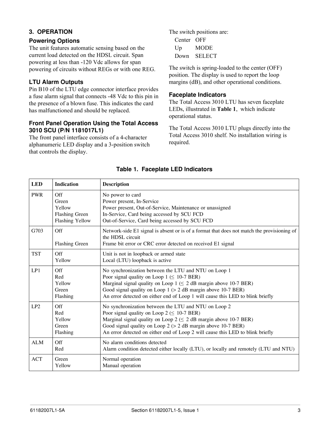
The Total Access 3010 LTU has seven faceplate LEDs, illustrated in Table 1, which indicate operational status.
The Total Access 3010 LTU plugs directly into the Total Access 3010 shelf. No installation wiring is required.
|
| Table 1. Faceplate LED Indicators |
|
|
|
LED | Indication | Description |
|
|
|
PWR | Off | No power to card |
| Green | Power present, |
| Yellow | Power present, |
| Flashing Green | |
| Flashing Yellow | |
|
|
|
G703 | Off | |
|
| the HDSL circuit |
| Flashing Green | Frame bit error or CRC error detected on received E1 signal |
|
|
|
TST | Off | Unit is not in loopback or armed state |
| Yellow | Local (LTU) loopback is active |
|
|
|
LP1 | Off | No synchronization between the LTU and NTU on Loop 1 |
| Red | Poor signal quality on Loop 1 (≤ |
| Yellow | Marginal signal quality on Loop 1 (≤ 2 dB margin above |
| Green | Good signal quality on Loop 1 (> 2 dB margin above |
| Flashing | An error detected on either end of Loop 1 will cause this LED to blink briefly |
|
|
|
LP2 | Off | No synchronization between the LTU and NTU on Loop 2 |
| Red | Poor signal quality on Loop 2 (≤ |
| Yellow | Marginal signal quality on Loop 2 (≤ 2 dB margin above |
| Green | Good signal quality on Loop 2 (> 2 dB margin above |
| Flashing | An error detected on either end of Loop 2 will cause this LED to blink briefly |
|
|
|
ALM | Off | No alarm conditions detected |
| Red | Alarm condition detected either locally (LTU), or locally and remotely (LTU and NTU) |
|
|
|
ACT | Green | Normal operation |
| Yellow | Manual operation |
|
|
|
Section | 3 |
