Predicting performance based upon signal quality varies with each loop. Generally, a noise margin of 0 or higher will support a bit error rate (BER) of better than
Table 3. LP1 and LP2 Guidellines
Margin | Color | Quality |
|
|
|
Margin < 0 | Red | Poor Loop Quality |
|
|
|
0 < Margin < 2 | Yellow | Marginal Loop Quality |
|
|
|
Margin > 2 | Green | Good Loop Quality |
|
|
|
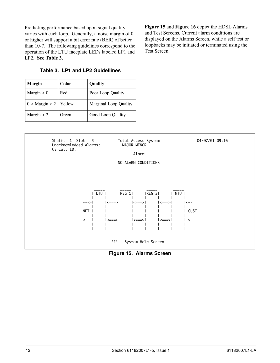
Figure 15 and Figure 16 depict the HDSL Alarms and Test Screens. Current alarm conditions are displayed on the Alarms Screen, while a self test or loopbacks may be initiated or terminated using the Test Screen.
Shelf: 1 Slot: 5 |
| Total Access System |
| 04/07/01 09:16 | |||
Unacknowledged Alarms: |
|
| MAJOR MINOR |
|
|
| |
Circuit ID: |
|
|
|
|
|
|
|
|
|
|
| Alarms |
|
|
|
|
| NO ALARM CONDITIONS |
|
| |||
_____ |
|
| _____ |
| _____ |
| _____ |
LTU | REG 1 | REG 2 | NTU | ||||
<===> | <===> | <===> | |||||
NET | CUST | ||||||
<===> | <===> | <===> | |||||
_____ | _____ | _____ | _____ | ||||
‘?’ - System Help Screen
Figure 15. Alarms Screen
12 | Section |