The HDSL local loop operates as two independent subsystems each operating over a single twisted pair. The LTU communicates over these two twisted pairs to the HDSL Transceiver Unit - Remote end (NTU). Each subsystem carries half of the total bandwidth along with a small amount of overhead used for maintenance and performance monitoring.
System power and alarm bus connections are made through the backplane of the Total Access 3010 shelf. E1 and HDSL signals are connected through the 50- pin shelf connectors related to each individual slot.
The LTU contains onboard fuses. If a fuse opens, it supplies a
The Total Access 3010 LTU uses a
NTU at less than
REVISION HISTORY
This is the first issue of this practice. Future changes to this document will be summarized in this paragraph.
2. INSTALLATION 
C A U T I O N !
SUBJECT TO ELECTROSTATIC DAMAGE
OR DECREASE IN RELIABILITY.
HANDLING PRECAUTIONS REQUIRED.
After unpacking the unit, inspect it for damage. If damage is discovered, file a claim with the carrier, then contact ADTRAN. See Warranty and Customer Service.
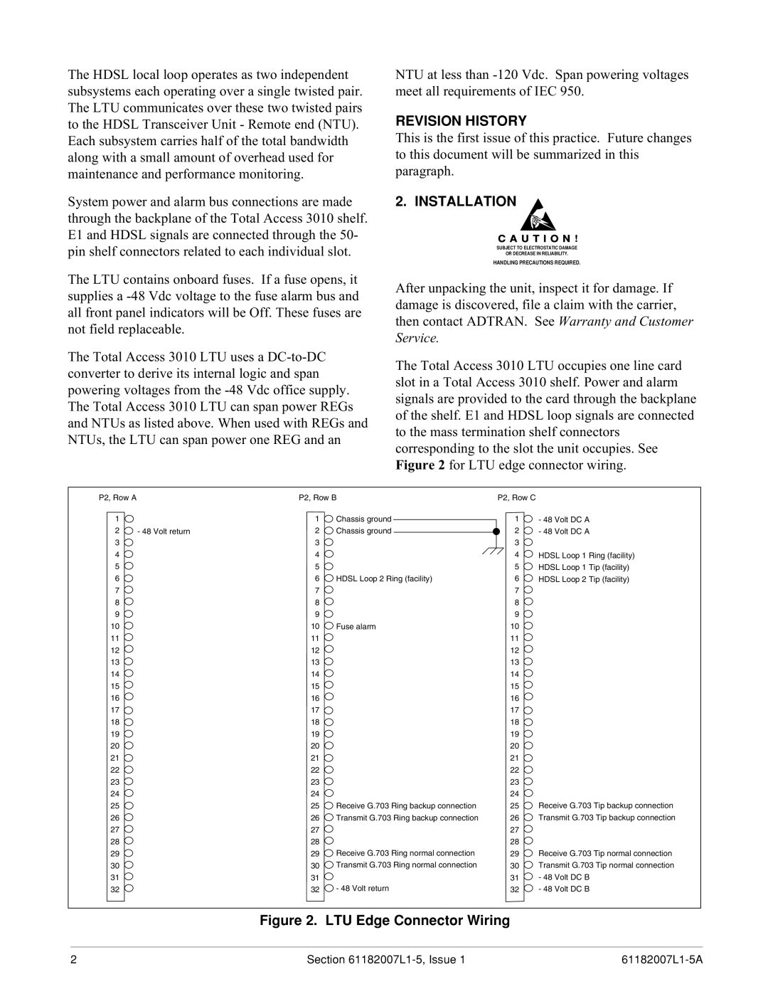
The Total Access 3010 LTU occupies one line card slot in a Total Access 3010 shelf. Power and alarm signals are provided to the card through the backplane of the shelf. E1 and HDSL loop signals are connected to the mass termination shelf connectors corresponding to the slot the unit occupies. See Figure 2 for LTU edge connector wiring.
P2, Row A |
| P2, Row B | P2, Row C |
| |
1 |
| 1 | Chassis ground | 1 | - 48 Volt DC A |
2 | - 48 Volt return | 2 | Chassis ground | 2 | - 48 Volt DC A |
3 |
| 3 |
| 3 |
|
4 |
| 4 |
| 4 | HDSL Loop 1 Ring (facility) |
5 |
| 5 |
| 5 | HDSL Loop 1 Tip (facility) |
6 |
| 6 | HDSL Loop 2 Ring (facility) | 6 | HDSL Loop 2 Tip (facility) |
7 |
| 7 |
| 7 |
|
8 |
| 8 |
| 8 |
|
9 |
| 9 |
| 9 |
|
10 |
| 10 | Fuse alarm | 10 |
|
11 |
| 11 |
| 11 |
|
12 |
| 12 |
| 12 |
|
13 |
| 13 |
| 13 |
|
14 |
| 14 |
| 14 |
|
15 |
| 15 |
| 15 |
|
16 |
| 16 |
| 16 |
|
17 |
| 17 |
| 17 |
|
18 |
| 18 |
| 18 |
|
19 |
| 19 |
| 19 |
|
20 |
| 20 |
| 20 |
|
21 |
| 21 |
| 21 |
|
22 |
| 22 |
| 22 |
|
23 |
| 23 |
| 23 |
|
24 |
| 24 |
| 24 |
|
25 |
| 25 | Receive G.703 Ring backup connection | 25 | Receive G.703 Tip backup connection |
26 |
| 26 | Transmit G.703 Ring backup connection | 26 | Transmit G.703 Tip backup connection |
27 |
| 27 |
| 27 |
|
28 |
| 28 |
| 28 |
|
29 |
| 29 | Receive G.703 Ring normal connection | 29 | Receive G.703 Tip normal connection |
30 |
| 30 | Transmit G.703 Ring normal connection | 30 | Transmit G.703 Tip normal connection |
31 |
| 31 |
| 31 | - 48 Volt DC B |
32 |
| 32 | - 48 Volt return | 32 | - 48 Volt DC B |
Figure 2. LTU Edge Connector Wiring
2 | Section |