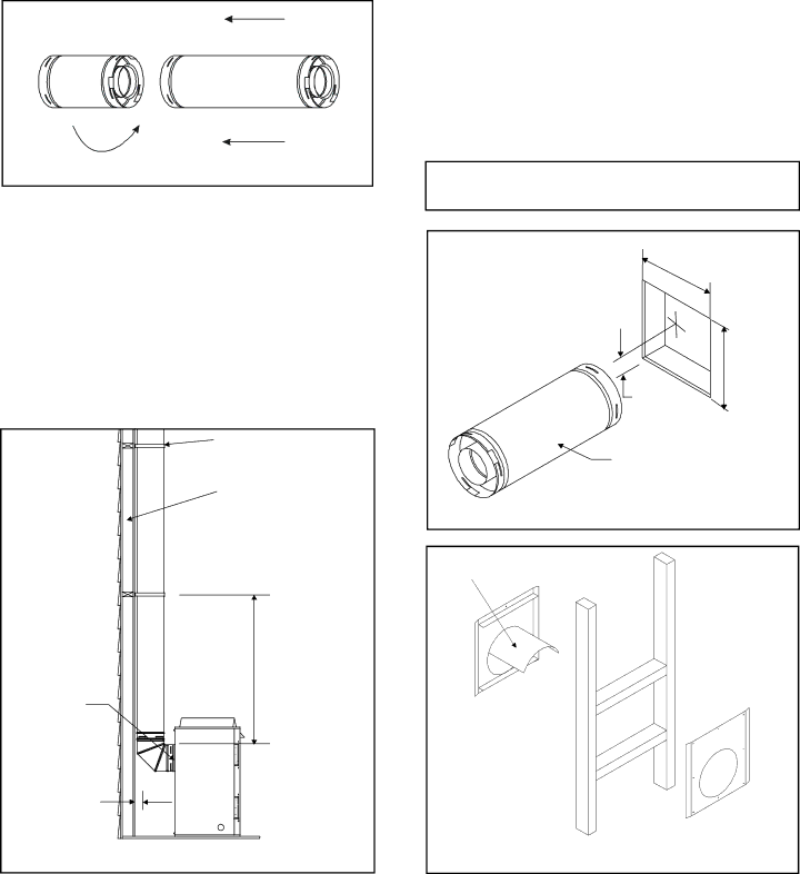
2. Continue Adding Vent Components
•Continue adding vent components, locking each succeed- ing component into place.
•Ensure that each succeeding vent component is secure- ly fitted and locked into the preceding component.
•90° elbows may be installed and rotated to any point around the preceding component’s vertical axis. If an el- bow does not end up in a locked position with the pre- ceding component, attach with a minimum of two (2) sheet metal screws.
Figure 23. Adding Venting Components
3. Install Support Brackets
For Horizontal Runs - The vent system must be supported every five (5) feet of horizontal run by a horizontal pipe support.
To install support brackets for horizontal runs:
•Place the pipe supports around the vent pipe.
•Nail the pipe supports to the framing members.
For Vertical Runs - The vent system must be supported every eight (8) feet (2.4m) above the fireplace flue outlet by wall brackets. To install support brackets for vertical runs:
•Attach wall brackets to the vent pipe and secure the wall bracket to the framing members with nails or screws.
WALL BRACKET |
WALL STUD |
4. Install Firestops
For Horizontal Runs - Firestops are REQUIRED on both sides of a combustible wall through which the vent passes.
NOTE: Model
To install firestops for horizontal runs that pass through either interior or exterior walls:
Cut a
mm)hole for
•Position the firestops on both sides of the hole previ- ously cut and secure the firestops with nails or screws.
•The heat shields of the firestops MUST BE placed to- wards the top of the hole.
•Continue the vent run through the firestops.
NOTE: There must be NO INSULATION or other combus- tibles inside the framed firestop opening.
12" or 10"
(305mm or 254mm)
1" (25.4 mm)
12" or 10" (305mm or 254mm)
VENT PIPE
Figure 25. Hole and Vent Pipe
8 FT. (2.4m) |
FLUE |
OUTLET |
1 INCH MIN. |
(25.4mm) |
HEAT SHIELD
INTERIOR
FIRESTOP
TRIM HEAT SHIELD IF TOO LONG, ADD TO SHIELD IF TOO SHORT
EXTERIOR
FIRESTOP
Figure 24. Installing Support Brackets
Figure 26. Heat Shield, Interior & Exterior Firestops
27
