LTU |
|
| ||
|
|
| AIS |
|
G.703 | LOCAL |
| G.703 |
|
LOOP |
|
| ||
|
| X |
| |
| LTU | NTU |
| |
|
|
| ||
NTU |
|
| ||
|
|
| AIS |
|
G.703 | LOCAL |
| G.703 |
|
LOOP |
|
| ||
|
| X |
| |
| LTU | NTU |
| |
|
|
| ||
NTU |
|
| ||
X | LOCAL |
|
|
|
AIS |
| G.703 |
| |
LOOP |
|
| ||
|
|
|
| |
| LTU | NTU |
|
|
LTU |
|
| ||
X | LOCAL |
|
|
|
AIS |
| G.703 |
| |
LOOP |
|
| ||
|
|
|
| |
| LTU | NTU |
|
|
LTU and NTU Bilateral Loopback |
| |||
G.703 | LOCAL |
| G.703 |
|
LOOP |
|
| ||
|
|
|
| |
| LTU | NTU |
|
|
REG |
|
|
| |
|
|
| AIS |
|
G.703 |
|
| G.703 |
|
LTU | REG |
| X |
|
| NTU |
| ||
Dual REG |
|
|
| |
|
|
| X | AIS |
|
|
|
| |
G.703 |
|
|
|
|
|
|
| X | G.703 |
LTU | REG | REG | NTU | |
| X = Signal Inactive |
|
| |
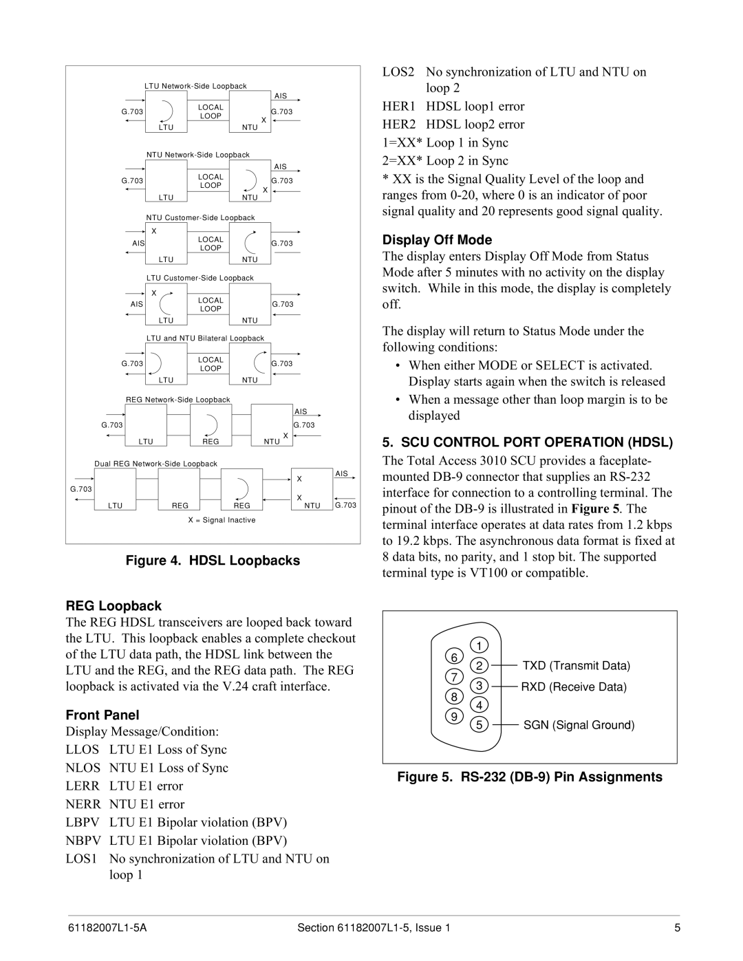
Figure 4. HDSL Loopbacks
REG Loopback
The REG HDSL transceivers are looped back toward the LTU. This loopback enables a complete checkout of the LTU data path, the HDSL link between the LTU and the REG, and the REG data path. The REG loopback is activated via the V.24 craft interface.
LOS2 No synchronization of LTU and NTU on loop 2
HER1 HDSL loop1 error HER2 HDSL loop2 error 1=XX* Loop 1 in Sync 2=XX* Loop 2 in Sync
*XX is the Signal Quality Level of the loop and ranges from
Display Off Mode
The display enters Display Off Mode from Status Mode after 5 minutes with no activity on the display switch. While in this mode, the display is completely off.
The display will return to Status Mode under the following conditions:
•When either MODE or SELECT is activated. Display starts again when the switch is released
•When a message other than loop margin is to be displayed
5.SCU CONTROL PORT OPERATION (HDSL)
The Total Access 3010 SCU provides a faceplate- mounted
1 |
|
6 | TXD (Transmit Data) |
2 | |
7 | RXD (Receive Data) |
3 |
Front Panel
Display Message/Condition: LLOS LTU E1 Loss of Sync
8
9
4
5 SGN (Signal Ground)
NLOS NTU E1 Loss of Sync LERR LTU E1 error NERR NTU E1 error
LBPV LTU E1 Bipolar violation (BPV) NBPV LTU E1 Bipolar violation (BPV)
LOS1 No synchronization of LTU and NTU on loop 1
Figure 5. RS-232 (DB-9) Pin Assignments
Section | 5 |