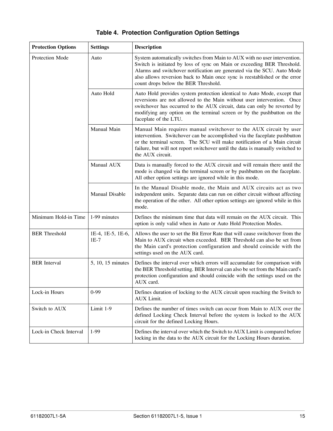
Table 4. Protection Configuration Option Settings
Protection Options | Settings | Description |
|
|
|
Protection Mode | Auto | System automatically switches from Main to AUX with no user intervention. |
|
| Switch is initiated by loss of sync on Main or exceeding BER Threshold. |
|
| Alarms and switchover notification are generated via the SCU. Auto Mode |
|
| also allows reversion back to Main once sync is reestablished or the error |
|
| count drops below the BER Threshold. |
|
|
|
| Auto Hold | Auto Hold provides system protection identical to Auto Mode, except that |
|
| reversions are not allowed to the Main without user intervention. Once |
|
| switchover has occurred to the AUX circuit, data can only be reverted by |
|
| modifying any option on the terminal screen or by the pushbutton on the |
|
| faceplate of the LTU. |
|
|
|
| Manual Main | Manual Main requires manual switchover to the AUX circuit by user |
|
| intervention. Switchover can be accomplished via the faceplate pushbutton |
|
| or the terminal screen. The SCU will make notification of a Main circuit |
|
| failure, but will not report switchover until the data is manually switched to |
|
| the AUX circuit. |
|
|
|
| Manual AUX | Data is manually forced to the AUX circuit and will remain there until the |
|
| mode is changed via the terminal screen or by pushbutton on the faceplate. |
|
| All other option settings are ignored while in this mode. |
|
|
|
|
| In the Manual Disable mode, the Main and AUX circuits act as two |
| Manual Disable | independent units. Separate data can run on either circuit without affecting |
|
| the operation of the other. All other option settings are ignored while in this |
|
| mode. |
|
|
|
Minimum | Defines the minimum time that data will remain on the AUX circuit. This | |
|
| option is only valid when in Auto or Auto Hold Protection Modes. |
|
|
|
BER Threshold | Allows the user to set the Bit Error Rate that will cause switchover from the | |
| Main to AUX circuit when exceeded. BER Threshold can also be set from | |
|
| the Main card's protection configuration and should coincide with the |
|
| settings used on the AUX card. |
|
|
|
BER Interval | 5, 10, 15 minutes | Defines the interval over which errors will accumulate for comparison with |
|
| the BER Threshold setting. BER Interval can also be set from the Main card's |
|
| protection configuration and should coincide with the settings used on the |
|
| AUX card. |
|
|
|
Defines duration of locking to the AUX circuit upon reaching the Switch to | ||
|
| AUX Limit. |
|
|
|
Switch to AUX | Limit | Defines the number of times switch can occur from Main to AUX over the |
|
| defined Locking Check Interval before the system is locked to the AUX |
|
| circuit for the defined Locking Hours. |
|
|
|
Defines the interval over which the Switch to AUX Limit is compared before | ||
|
| locking in the data to the AUX circuit for the Locking Hours duration. |
|
|
|
Section | 15 |