Manuals
/
Advantech
/
Computer Equipment
/
Computer Hardware
Advantech
PCI-1625U
user manual
Click Finish to complete the installation
Models:
PCI-1625U
1
24
52
52
Download
52 pages
31.5 Kb
21
22
23
24
25
26
27
28
Specification
Install
Pin Assignments & Wiring
Warranty
Hardware Configuration
Accessories
Driver Setup
Using the Icom Tools Utility
Page 24
Image 24
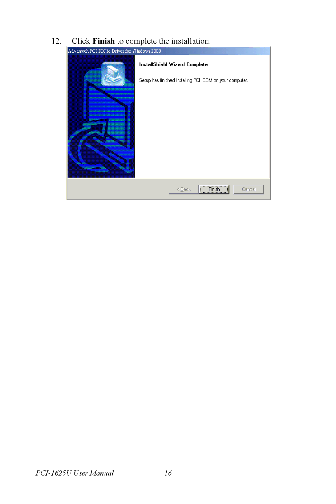
12.
Click
Finish
to complete the installation.
PCI-1625U
User Manual
16
Page 23
Page 25
Page 24
Image 24
Page 23
Page 25
Contents
PCI-1625U
Port Intelligent RS-232 Universal PCI Communication Card
Copyright Acknowledgements
Product Warranty 2 years
FCC Class a Technical Support and Assistance
Safety Precaution Static Electricity
Packing List
Page
Contents
Pin Assignments & Wiring
Introduction
Description
Features
Specifications
ESD Protection 16 kV Dimensions 175 x 100 mm
Operating Temperature 0~ 60 C 32~140 F
Accessories
Ordering Information
PCI Intelligent Communication Card
Hardware Configuration
Initial Inspection
Card Installation
Page
Driver Setup Installation
Driver Setup
Introduction
Steps for Windows 2000/XP Driver Setup
Page
Page
Page
Page
Click Finish to complete the installation
Verifying Driver Installation
Tion port numbers
Page
Page
Removing PCI Icom Series Device
You must remove all used ports setting and device
Driver Uninstallation
Icom Tools
Installation
User Interface of Icom Tools
Menu Bar
All Ports Submenu
Tool Bar
Com Port Tab
Transfer Modes
Port Status
Message Logo
Tx Slide Bar
Performance Listing Area
Status Bar
Using the Icom Tools Utility
Port Selection
Select Port dialog box
Configuring a Port
Icom Tools User Interface
Run the Test
Test Information on the Performance Listing Area
Close Port
Exit the Icom Tools utility
Performance Listing Area
Stop the Test
Messages on Status Bar and Message Logo Area
Status Bar Messages
Message Logo Messages
Pin Assignments & Wiring
Pin Assignments
PCI-1625U
PCI-1625U RS-232 Mode DB62 Pin Description
PCI-1625U with OPT8AP
PCI-1625U with OPT8BP, OPT8C
PCI-1625U with OPT8H
PCI-1625U with OPT8FP
Wiring
Modem Connections
Top
Page
Image
Contents