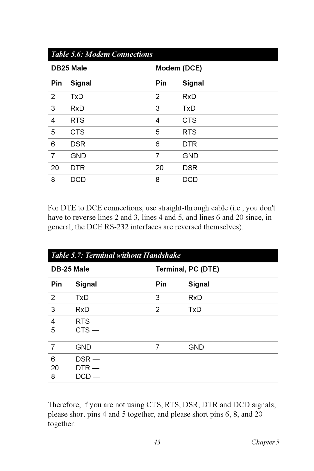
Table 5.6: Modem Connections
DB25 Male | Modem (DCE) | ||
|
|
|
|
Pin | Signal | Pin | Signal |
|
|
|
|
2 | TxD | 2 | RxD |
|
|
|
|
3 | RxD | 3 | TxD |
|
|
|
|
4 | RTS | 4 | CTS |
|
|
|
|
5 | CTS | 5 | RTS |
|
|
|
|
6 | DSR | 6 | DTR |
|
|
|
|
7 | GND | 7 | GND |
|
|
|
|
20 | DTR | 20 | DSR |
|
|
|
|
8 | DCD | 8 | DCD |
|
|
|
|
For DTE to DCE connections, use
Table 5.7: Terminal without Handshake
Terminal, PC (DTE) | |||
|
|
|
|
Pin | Signal | Pin | Signal |
|
|
|
|
2 | TxD | 3 | RxD |
|
|
|
|
3 | RxD | 2 | TxD |
4RTS —
5CTS —
7 | GND | 7 | GND |
6 | DSR — |
|
|
20 | DTR — |
|
|
8DCD —
Therefore, if you are not using CTS, RTS, DSR, DTR and DCD signals, please short pins 4 and 5 together, and please short pins 6, 8, and 20 together.
43 | Chapter5 |
