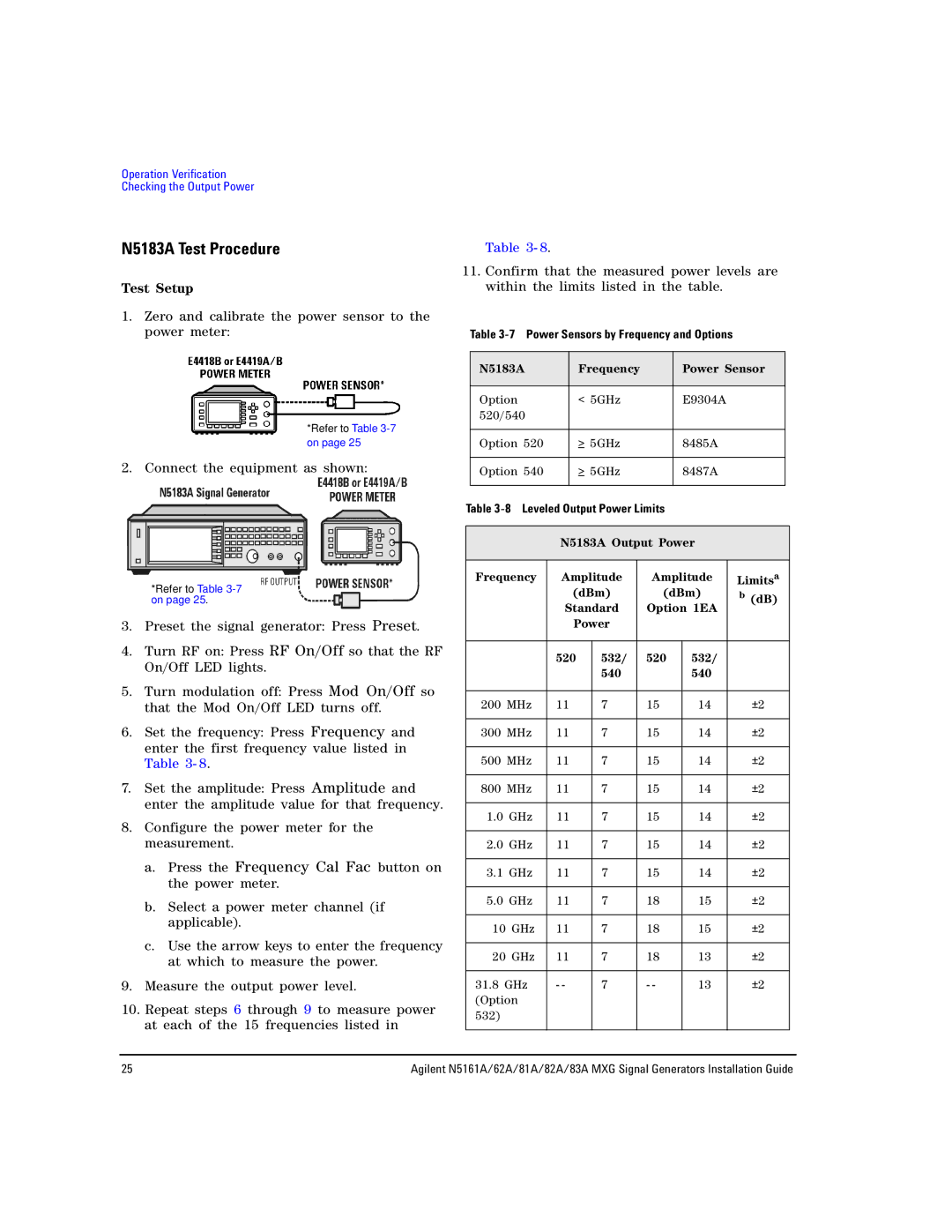
81A, 82A, 83A, 62A, N5161A specifications
Agilent Technologies, now part of Keysight Technologies, is renowned for its advanced electronic test and measurement solutions. Among its offerings, the 83A, N5161A, 62A, 82A, and 81A signal generation and analysis instruments stand out for their performance, reliability, and innovative technologies tailored for various applications.The Agilent 83A is a versatile RF signal generator designed for lab environments and production lines. Its main features include wide frequency coverage, low phase noise, and frequency accuracy, making it suitable for testing wireless communications, radar, and military applications. The use of advanced digital signal processing ensures high output stability and purity, crucial for testing complex modulation schemes.
The N5161A, part of the EXG series, is a signal generator that combines exceptional performance with extensive functionality. It offers frequency coverage from 250 kHz to 6 GHz and includes capabilities for creating complex waveforms. Its built-in arbitrary waveform generator allows users to define custom signals, enhancing testing versatility. The integrated software support streamlines programming and automation, which is vital for production testing environments.
The Agilent 62A is designed specifically for microwave applications, offering frequency ranges up to 40 GHz. One of its standout features is its ability to generate signals with remarkably low phase noise, making it suitable for applications that require high precision, such as aerospace and defense. It also features multi-channel capability, allowing simultaneous testing of multiple devices, which increases throughput in high-demand environments.
The 82A signal generator is frequently used in educational and research settings due to its user-friendly interface and cost-effectiveness. It provides several modulation options, including AM, FM, and PM, making it an excellent choice for experimentation and learning purposes. The device’s compact design ensures that it fits well in diverse laboratory setups.
Lastly, the Agilent 81A is known for its compact size and portability, making it highly suitable for field applications. It features basic signal generation capabilities and is designed for ease of use, providing engineers with a reliable tool for quick tests and measurements in various locations.
In conclusion, Agilent Technologies' 83A, N5161A, 62A, 82A, and 81A signal generation instruments exemplify innovation in electronic measurement. Each model possesses unique features and capabilities, allowing engineers to choose the right tool for their specific testing needs across numerous industries, from telecommunications to aerospace. With an emphasis on precision, flexibility, and advanced technology, these instruments continue to play a vital role in the evolution of electronic test solutions.

