ENGLISH
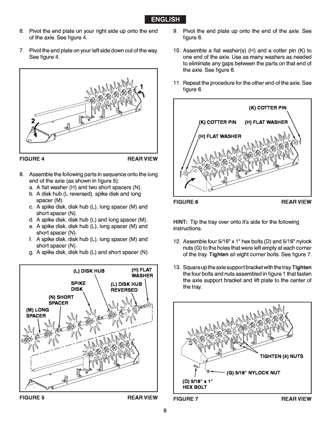
6.Pivot the end plate on your right side up onto the end of the axle. See figure 4.
7.Pivot the end plate on your left side down out of the way.
See figure 4.
| 1 |
2 |
|
FIGURE 4 | REAR VIEW |
8.Assemble the following parts in sequence onto the long end of the axle (as shown in figure 5):
a.A flat washer (H) and two short spacers (N).
b.A disk hub (L reversed), spike disk and long spacer (M).
c.A spike disk, disk hub (L), long spacer (M) and short spacer (N).
d.A spike disk, disk hub (L) and long spacer (M).
e.A spike disk, disk hub (L), long spacer (M) and short spacer (N).
f.A spike disk, disk hub (L), long spacer (M) and short spacer (N).
g.A spike disk, disk hub (L) and short spacer (N).
(L) DISK HUB | (H) FLAT |
| WASHER |
SPIKE | (L) DISK HUB |
DISK | REVERSED |
(N) SHORT |
|
SPACER |
|
(M) LONG |
|
SPACER |
|
FIGURE 5 | REAR VIEW |
9.Pivot the end plate up onto the end of the axle. See figure 6.
10.Assemble a flat washer(s) (H) and a cotter pin (K) to one end of the axle. Use as many washers as needed to eliminate any gaps between the parts on that end of the axle. See figure 6.
11.Repeat the procedure for the other end of the axle. See figure 6.
| (K) COTTER PIN |
(K) COTTER PIN | (H) FLAT WASHER |
(H) FLAT WASHER |
|
FIGURE 6 | REAR VIEW |
HINT: Tip the tray over onto it's side for the following instructions.
12.Assemble four 5/16" x 1" hex bolts (D) and 5/16" nylock nuts (G) to the holes that were left empty at each corner of the tray. Tighten all eight corner bolts. See figure 7.
13.Square up the axle support bracket with the tray.Tighten the four bolts and nuts assembled in figure 1 that fasten the axle support bracket and lift plate to the center of the tray.
| TIGHTEN (4) NUTS |
| (G) 5/16" NYLOCK NUT |
(D) 5/16" x 1" |
|
HEX BOLT |
|
FIGURE 7 | REAR VIEW |