1
GH-DA/A
CN | 1 | ON |
| 3 | 4 |
|
| 2 | |||
|
| 1 |
|
| |
| CN2 |
|
|
|
|
1 | 0 |
2
CN2
CN1
1
CN3
CN1
2
![]() GH-NS
GH-NS
CN1
CN2
CN1CN3
![]() CN100 CN2
CN100 CN2
3
|
| ||||
|
|
|
|
|
|
|
|
|
|
|
|
|
|
|
|
|
|
|
|
|
|
|
|
|
|
|
|
|
|
|
|
|
|
|
|
3
CN2 | CN1 |
CN1 | CN2 |
CN2 | CN1 |
CN1 | CN2 |
CN2 | CN1 |
4
5
CN | 1 | ON |
| 3 | 4 |
|
| 1 | 2 |
|
|
| CN2 |
|
|
|
|
1 | 0 |
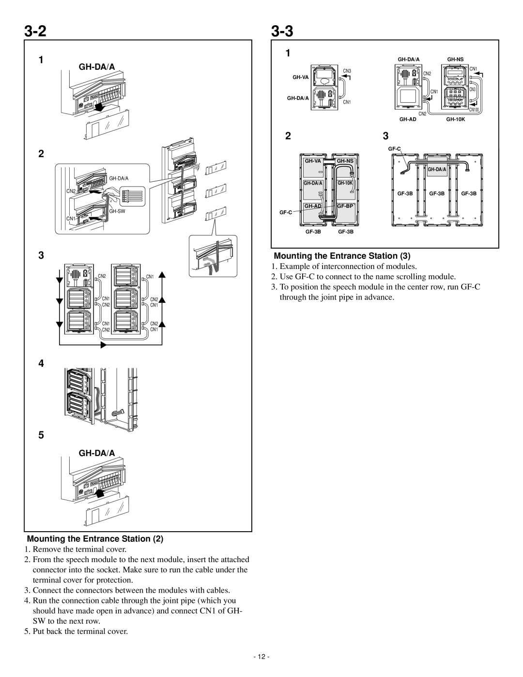
Mounting the Entrance Station (2)
1.Remove the terminal cover.
2.From the speech module to the next module, insert the attached connector into the socket. Make sure to run the cable under the terminal cover for protection.
3.Connect the connectors between the modules with cables.
4.Run the connection cable through the joint pipe (which you should have made open in advance) and connect CN1 of GH- SW to the next row.
5.Put back the terminal cover.
Mounting the Entrance Station (3)
1.Example of interconnection of modules.
2.Use
3.To position the speech module in the center row, run
- 12 -
