Expanded System
1.Common trunk line: maximum of 2 trunk lines
2.Sub trunk line: maximum of 4 trunk lines
Maximum of 125 units (maximum of 48 units for standard system)
•The wiring of the sub trunk line is the same as the standard system. For details, see
[1] Entrance Station
•Basic System #1 - #5
•Expanded System (#1 - #8) x 2
![]() When installing multiple entrance stations, make sure to set the
When installing multiple entrance stations, make sure to set the
[2]Security guard station
• Standard System #1, #2
• Expanded System (#1, #2) x 2
![]() When installing plural security guard stations, make sure to set the ID numbers (SW1).
When installing plural security guard stations, make sure to set the ID numbers (SW1).
[3]Expanded video Bus control unit
Connector cable length: 40 cm
[4]Expanded Bus control unit
For connecting the lift control adaptor
[5]Bus control unit
[6]Distribution terminal (junction): not included
[7]Power supply
NP:
NOTE: For communication between Entrance station and Residential station, one each communication path is available to "COMMON1 - SUB1" and "COMMON2 - SUB2". In case of crossover communication such as "COMMON1 - SUB2" or "COMMON2 - SUB1", it occupies entire communication path in the system.
[1] |
| [2] |
|
|
|
GH-RY
[5]
[3]
[4]
|
|
|
|
|
|
|
|
|
|
|
|
|
|
|
|
|
|
B |
|
|
|
| |
|
| AC | |||
[6]
[7]
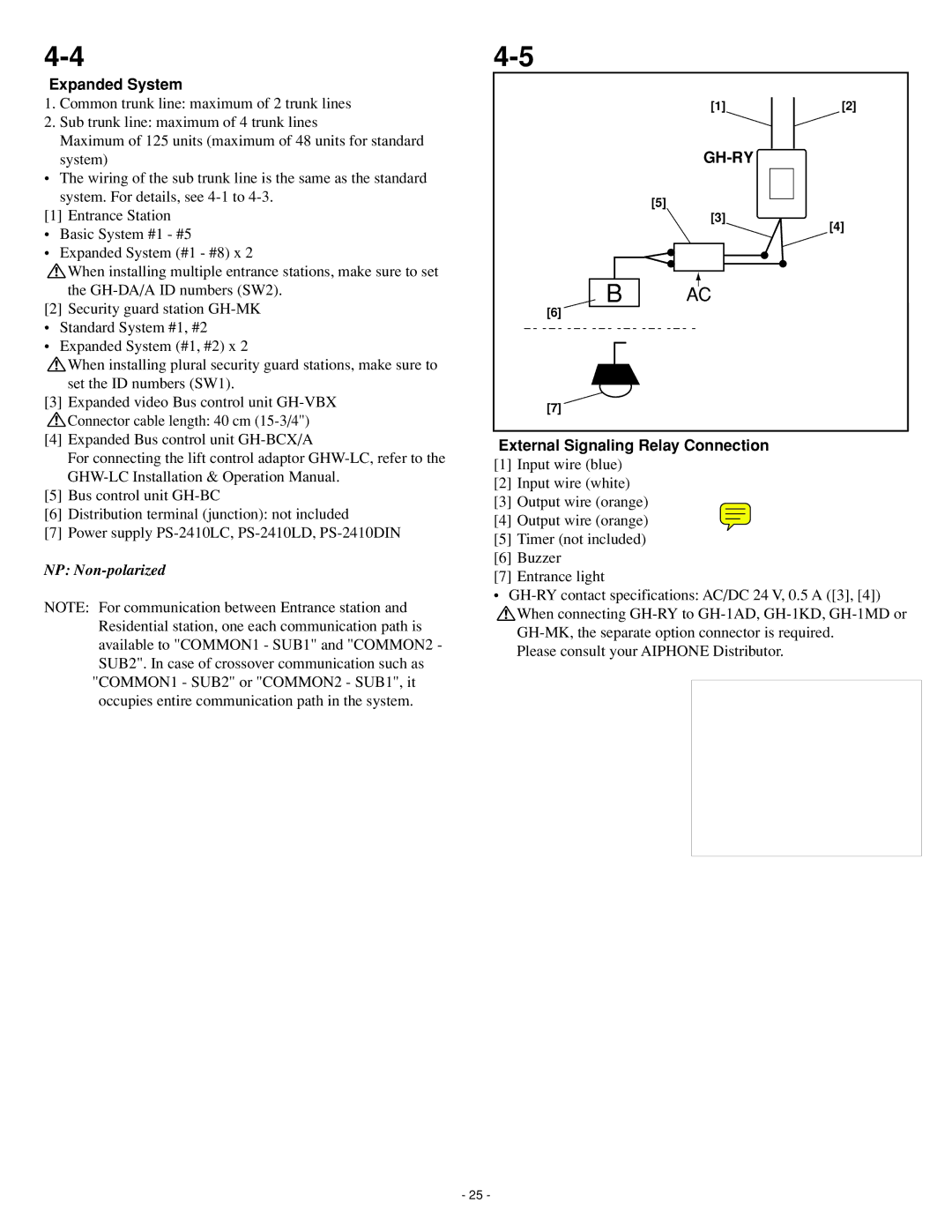
External Signaling Relay Connection
[1]Input wire (blue)
[2]Input wire (white)
[3]Output wire (orange)
[4]Output wire (orange)
[5]Timer (not included)
[6]Buzzer
[7]Entrance light
•
![]() When connecting
When connecting
Please consult your AIPHONE Distributor.
- 25 -