Expanded System Configuration Diagram
1.Common trunk line #1, 2
2.Sub trunk line #1 - 4
Sub trunk line #2 - #4 are the same as #1. Maximum 125 units per sub trunk line.
(1)Audio signal line
(2)Video signal line
(3)Power supply line
a.Entrance station (For details, see
b.Bus control unit
c.Residential station (For details, see
d.Residential station (For details, see
![]() Do not mix
Do not mix
e.Security Guard Station
f.Expanded Bus control unit
[1]Expanded video Bus control unit
[2]Expanded Bus control unit
[3]Distribution terminal (junction): Not included
[4]Power supply
| Capacity |
Entrance Station | Maximum 16 stations |
| (up to 3 stations per trunk) |
|
|
Residential stations | Maximum 125 stations |
per Sub trunk line | (up to 25 stations per trunk) |
Residential Station | Maximum 500 stations |
Security Guard Station | Maximum 4 stations |
Residential stations | Maximum 4 stations |
in the same residence | (up to 2 monitor stations) |
Bus control unit | Maximum 1 unit |
per Common trunk line |
|
Bus control unit | Maximum 1 unit |
per Sub trunk line |
|
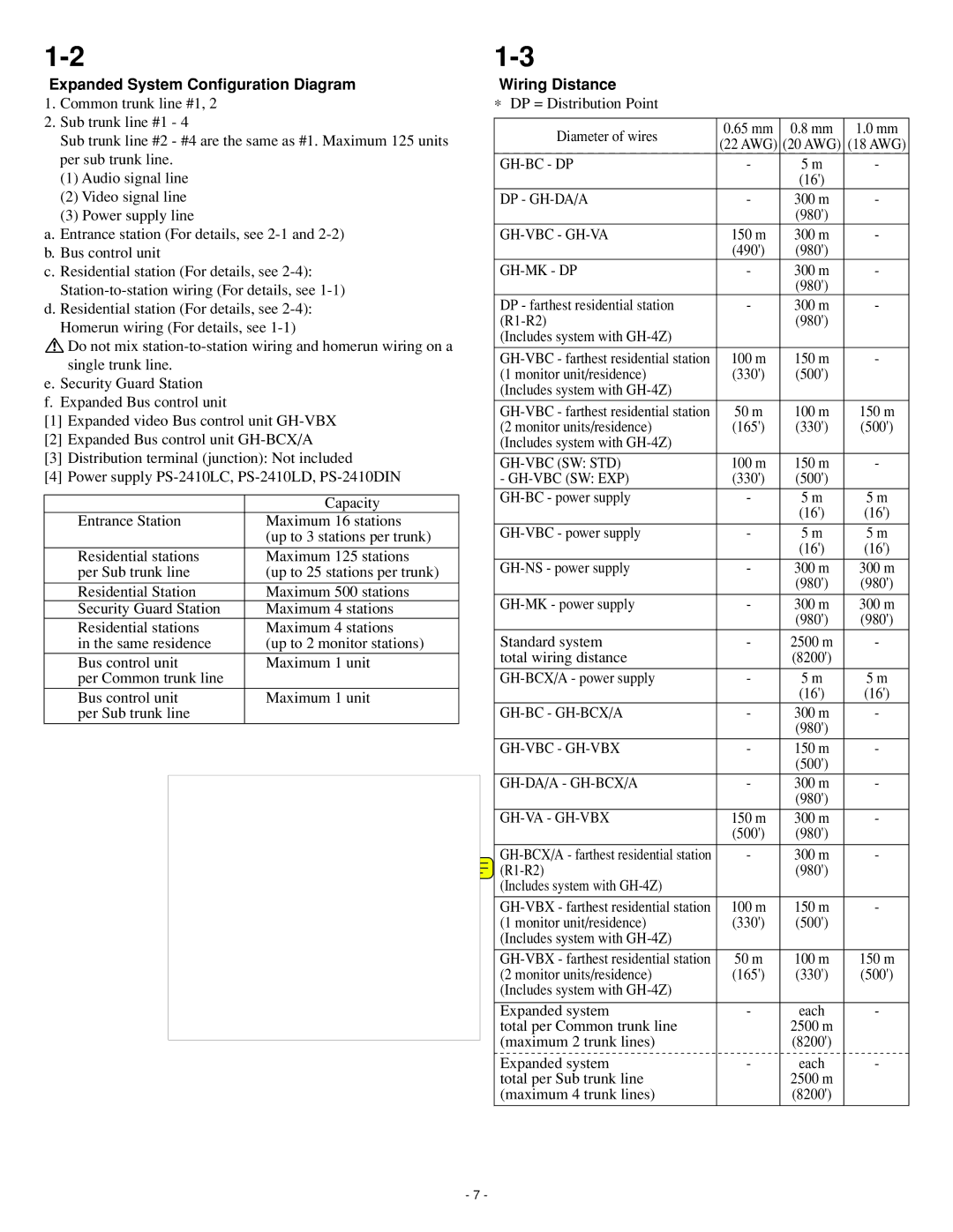
Wiring Distance
∗ DP = Distribution Point
Diameter of wires | 0.65 mm | 0.8 mm | 1.0 mm | |
(22 AWG) | (20 AWG) | (18 AWG) | ||
| ||||
- | 5 m | - | ||
|
| (16') |
| |
DP - | - | 300 m | - | |
|
| (980') |
| |
150 m | 300 m | - | ||
| (490') | (980') |
| |
| - | 300 m | - | |
|
| (980') |
| |
DP - farthest residential station | - | 300 m | - | |
| (980') |
| ||
(Includes system with |
|
|
| |
|
|
|
| |
100 m | 150 m | - | ||
(1 monitor unit/residence) | (330') | (500') |
| |
(Includes system with |
|
|
| |
50 m | 100 m | 150 m | ||
(2 monitor units/residence) | (165') | (330') | (500') | |
(Includes system with |
|
|
| |
100 m | 150 m | - | ||
- | (330') | (500') |
| |
- | 5 m | 5 m | ||
|
| (16') | (16') | |
|
|
|
| |
- | 5 m | 5 m | ||
|
| (16') | (16') | |
- | 300 m | 300 m | ||
|
| (980') | (980') | |
- | 300 m | 300 m | ||
|
| (980') | (980') | |
Standard system | - | 2500 m | - | |
total wiring distance |
| (8200') |
| |
|
|
|
| |
- | 5 m | 5 m | ||
|
| (16') | (16') | |
- | 300 m | - | ||
|
| (980') |
| |
- | 150 m | - | ||
|
| (500') |
| |
- | 300 m | - | ||
|
| (980') |
| |
| 150 m | 300 m | - | |
| (500') | (980') |
| |
|
|
|
| |
- | 300 m | - | ||
| (980') |
| ||
(Includes system with |
|
|
| |
100 m | 150 m | - | ||
(1 monitor unit/residence) | (330') | (500') |
| |
(Includes system with |
|
|
| |
|
|
|
| |
50 m | 100 m | 150 m | ||
(2 monitor units/residence) | (165') | (330') | (500') | |
(Includes system with |
|
|
| |
|
|
|
| |
Expanded system | - | each | - | |
total per Common trunk line |
| 2500 m |
| |
(maximum 2 trunk lines) |
| (8200') |
| |
Expanded system | - | each | - | |
total per Sub trunk line |
| 2500 m |
| |
(maximum 4 trunk lines) |
| (8200') |
|
- 7 -