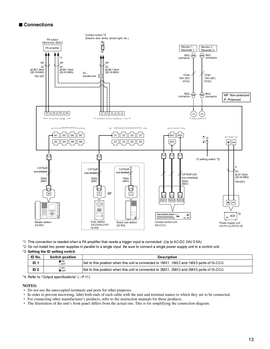
■Connections
|
| Contact output *4 |
|
| |
| PA output | (Electric door strike, strobe light, etc.) |
|
| |
|
|
|
|
| |
(50mVrms, 600Ω) |
|
|
|
| |
| PA amplifier |
|
| Monitor 1, | Monitor 2, |
|
|
| Recorder 1 | Recorder 2 | |
|
|
|
| ||
| *1 |
|
| BNC | BNC |
|
|
| connector | connector | |
NP | NP |
| NP |
|
|
2C | 2C |
| 2C |
|
|
|
|
| |||
AC | Coax | Coax | |||
15m (50') |
| transformer | PT | ||
| 15m (50') | 15m (50') | |||
|
|
|
| ||
|
|
|
| NTSC | NTSC |
|
|
|
| BNC | BNC |
|
|
|
| connector | connector |
NP: Non-polarized
P: Polarized
P1 ![]()
![]() P2
P2 ![]()
![]() P3
P3 ![]()
![]() P4
P4
L1 ![]()
![]() L2
L2 ![]()
![]() L3
L3
L4
V1 V2
PA OUTPUT (600Ω)
MASTER STATION
![]() M1
M1 ![]()
![]() M3
M3 ![]()
![]() M5
M5 ![]()
![]() M7
M7
M2 ![]()
![]() M4
M4 ![]()
![]() M6
M6 ![]()
![]() M8
M8
![]() CONTACT OUTPUT (AC/DC24V 0.5A)
CONTACT OUTPUT (AC/DC24V 0.5A) ![]()
VIDEO/AUDIO DOOR/SUB STATION
![]()
![]() D1
D1 ![]()
![]() D3
D3 ![]()
![]() D5
D5 ![]()
![]() D7
D7
D2 ![]()
![]() D4
D4 ![]()
![]() D6
D6 ![]()
![]() D8
D8
|
|
|
|
|
|
|
|
|
|
|
|
|
|
|
|
|
|
|
| VIDEO OUTPUT |
|
|
|
|
|
|
|
|
|
|
|
|
|
|
|
|
|
|
|
|
|
|
|
|
|
|
|
|
|
|
|
|
|
|
|
|
|
|
|
|
|
|
|
|
|
|
|
|
|
|
| ||
|
|
|
|
|
|
|
|
|
|
|
|
|
|
|
|
|
|
|
|
|
|
|
|
|
|
|
| |||||||||
|
|
|
|
|
|
|
|
|
|
|
|
|
|
|
|
|
|
|
|
|
|
|
|
|
|
|
|
| ||||||||
|
|
|
|
|
|
|
|
|
|
|
|
|
|
|
|
|
|
|
|
|
| |||||||||||||||
|
|
|
|
|
|
|
|
|
|
|
|
|
|
|
|
|
|
|
|
|
|
|
|
|
|
|
|
|
|
|
|
|
|
|
| |
|
|
|
|
|
|
|
|
|
|
|
|
|
|
|
|
|
|
|
|
|
|
|
|
|
|
|
|
|
|
|
|
|
|
|
|
|
| MX1 |
| MX3 |
|
|
|
|
|
|
|
|
|
|
|
|
|
|
|
|
|
|
|
| |||||||||||||
|
|
|
|
|
|
|
|
|
|
|
|
|
|
|
|
|
|
|
|
|
|
|
|
|
|
|
|
| DC48V |
|
|
| ||||
|
|
|
|
|
|
|
|
|
|
|
|
| 1 | ID |
|
|
|
|
| |||||||||||||||||
|
|
|
|
|
|
|
|
|
|
|
|
|
|
|
|
|
|
| ||||||||||||||||||
| MX2 |
| 2 |
|
|
|
|
|
|
|
|
|
|
|
|
|
|
| ||||||||||||||||||
|
|
|
|
|
|
|
|
|
|
|
|
|
|
|
|
|
|
|
|
|
|
|
|
|
|
|
|
|
|
|
|
|
|
|
|
|
|
|
|
|
|
|
|
|
|
|
|
|
|
|
|
|
|
|
|
|
|
|
|
|
|
|
|
|
|
|
|
|
|
|
|
|
|
|
|
|
|
|
|
|
|
|
|
|
|
|
|
|
|
|
|
|
|
|
|
|
|
|
|
|
|
|
|
|
|
|
|
|
|
|
CAT5e/6
300m
(980')
M |
CAT5e/6
300m
(980')
D
CAT5e/6 |
|
|
|
|
|
|
|
|
|
|
|
|
|
|
|
|
|
|
|
|
| ID setting switch *3 |
|
|
|
|
|
|
|
|
| P | ||||
|
|
|
|
|
|
|
|
|
|
|
|
|
|
|
|
|
|
|
|
|
|
|
|
|
|
|
|
|
| |||||||
|
|
|
|
|
|
|
|
|
|
|
|
|
|
|
|
|
|
|
|
|
|
|
|
|
|
|
|
|
|
| ||||||
|
|
|
|
|
|
|
|
|
|
|
|
|
|
|
|
|
|
|
|
|
|
|
|
|
|
|
|
|
|
| 2C | |||||
|
|
|
|
|
|
|
|
|
|
|
|
|
|
|
|
|
|
| CAT5e/6 (x3) |
|
|
|
|
|
|
|
|
| ||||||||
|
|
|
|
|
|
|
|
|
|
|
|
|
|
|
|
|
|
|
|
|
|
|
|
|
|
|
|
|
|
| ||||||
150m |
|
|
|
|
|
|
|
|
|
|
|
|
|
|
|
|
|
|
|
|
|
|
|
|
|
|
| |||||||||
(490') |
|
|
|
|
|
|
|
|
|
|
|
|
|
|
|
|
|
|
| 200m |
|
|
|
|
|
|
|
|
| 15m(50') | ||||||
|
|
|
|
|
|
|
|
|
|
|
|
|
|
|
|
|
|
|
| (650') |
|
|
|
|
|
|
|
|
|
|
|
| ||||
or |
|
|
|
|
|
|
|
|
|
|
|
|
|
|
|
|
|
|
|
|
|
|
|
|
|
|
|
|
|
|
|
|
|
|
|
|
|
|
|
|
|
|
|
|
|
|
|
|
|
|
|
|
|
|
|
|
|
|
|
|
|
|
|
|
|
|
|
|
|
|
|
| |
|
| C |
|
|
|
|
|
|
|
|
|
|
|
|
|
|
|
|
|
|
|
|
|
|
|
|
|
|
|
|
|
|
|
| ||
|
|
|
|
|
|
|
|
|
|
|
|
|
|
|
|
|
|
|
|
|
|
|
|
|
|
|
|
|
|
|
|
|
|
|
|
|
|
|
|
|
|
|
|
|
|
|
|
|
|
|
|
|
|
|
|
|
|
|
|
|
|
|
|
|
|
|
|
|
|
|
|
|
|
|
|
|
|
|
| 1MX1 |
| 1MX2 |
| 1MX3 |
|
|
|
|
|
|
|
|
|
|
|
|
| |||||||||||||
|
|
|
| *2 |
Master station | Door station | Room sub station | Central control unit | Power supply unit |
|
|
|
|
*1: This connection is needed when a PA amplifier that needs a trigger input is connected. (Up to AC/DC 24V 0.5A)
*2: Do not install two power supplies in parallel to a single input. Be sure to connect a single power supply unit to a control unit.
*3: Setting the ID setting switch
ID No. | Switch position | Description |
ID 1 | ON | Set to this position when this unit is connected to 1MX1, 1MX2 and 1MX3 ports of |
OFF | ||
ID 2 | ON | Set to this position when this unit is connected to 2MX1, 2MX2 and 2MX3 ports of |
OFF | ||
|
|
|
*4: Refer to “Output specifications” (→P.11).
NOTES:
•Do not use the unoccupied terminals and ports for other purposes.
•In order to prevent miswiring, label both ends of each cable with the unit and terminal names to which they are to be connected.
•For connecting other manufacturer’s products, refer to the instruction manuals for those products.
•The illustration of the unit’s front panel differs from the actual one. This is for simplifying the connection diagram.
13