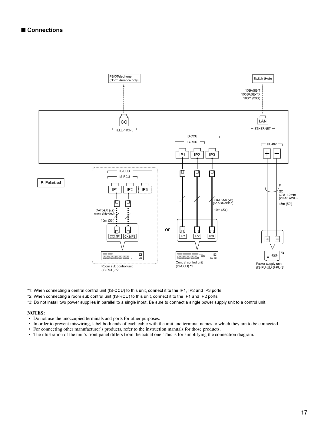
■Connections
PBX/Telephone (North America only)
Switch (Hub)
CO
LAN
![]() TELEPHONE
TELEPHONE ![]()
![]() ETHERNET
ETHERNET ![]()
![]() DC48V
DC48V ![]()
IP1
IP2
IP3
P: Polarized
|
|
|
|
|
|
|
|
|
|
|
|
|
|
| IP1 |
|
| IP2 |
| IP3 | |||||||
|
|
|
|
|
|
|
|
|
|
|
|
|
|
|
|
|
|
|
|
|
|
|
|
|
|
|
|
|
|
|
|
|
|
|
|
|
|
|
|
|
|
|
|
|
|
|
|
|
|
|
|
|
|
|
|
CAT5e/6 (x2)
10m (33')
or
CX1/IP1 ![]()
![]() CX2/IP2
CX2/IP2
IP1
IP2 |
CAT5e/6 (x3)
10m (33')
IP3 |
P
![]() 2C
2C
15m (50')
*3
| Central control unit | Power supply unit | |
Room sub control unit | |||
| |||
|
|
*1: When connecting a central control unit
*2: When connecting a room sub control unit
*3: Do not install two power supplies in parallel to a single input. Be sure to connect a single power supply unit to a control unit.
NOTES:
•Do not use the unoccupied terminals and ports for other purposes.
•In order to prevent miswiring, label both ends of each cable with the unit and terminal names to which they are to be connected.
•For connecting other manufacturer’s products, refer to the instruction manuals for those products.
•The illustration of the unit’s front panel differs from the actual one. This is for simplifying the connection diagram.
17