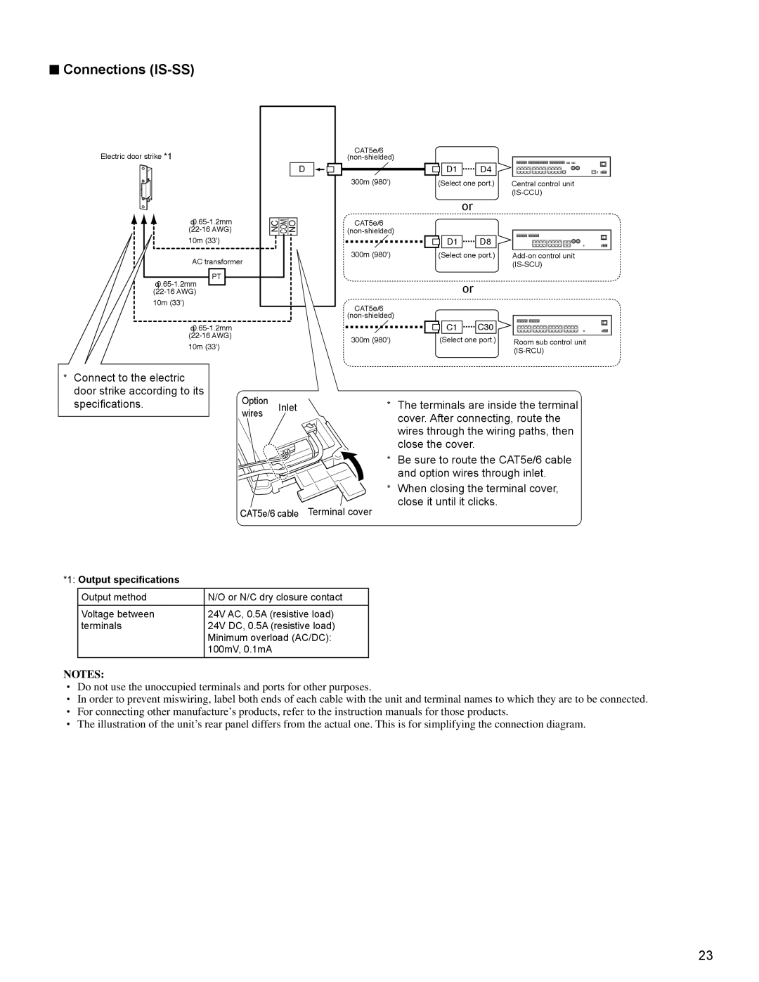
■Connections (IS-SS)
Electric door strike *1
10m (33')
AC transformer
PT
10m (33')
10m (33')
D
NO
COM
NC
CAT5e/6 |
|
|
|
|
|
| |
| D1 | D4 |
|
300m (980') | (Select one port.) | Central control unit | |
|
|
| |
|
| or |
|
CAT5e/6 |
|
|
|
|
|
| |
| D1 | D8 |
|
300m (980') | (Select one port.) | ||
|
|
| |
|
| or |
|
CAT5e/6 |
|
|
|
|
|
| |
| C1 | C30 |
|
300m (980') | (Select one port.) | Room sub control unit | |
|
|
| |
*Connect to the electric door strike according to its
specifications. | Option | Inlet |
| wires |
|
CAT5e/6 cable Terminal cover
*1: Output specifications
Output method | N/O or N/C dry closure contact |
Voltage between | 24V AC, 0.5A (resistive load) |
terminals | 24V DC, 0.5A (resistive load) |
| Minimum overload (AC/DC): |
| 100mV, 0.1mA |
*The terminals are inside the terminal cover. After connecting, route the wires through the wiring paths, then close the cover.
*Be sure to route the CAT5e/6 cable and option wires through inlet.
*When closing the terminal cover, close it until it clicks.
NOTES:
•Do not use the unoccupied terminals and ports for other purposes.
•In order to prevent miswiring, label both ends of each cable with the unit and terminal names to which they are to be connected.
•For connecting other manufacture’s products, refer to the instruction manuals for those products.
•The illustration of the unit’s rear panel differs from the actual one. This is for simplifying the connection diagram.
23