CONNECTIONS
System connection diagram
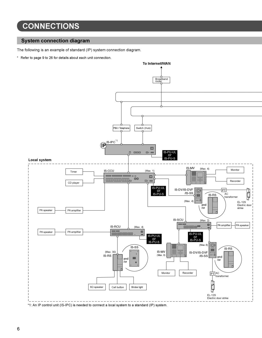
The following is an example of standard (IP) system connection diagram.
* Refer to page 9 to 26 for details about each unit connection.
To Internet/WAN
Broadband router
|
|
|
|
|
|
|
|
|
|
|
|
|
|
|
|
|
|
|
|
|
|
|
|
|
|
|
|
|
|
|
|
|
|
|
|
PBX / Telephone |
| Switch (Hub) | ||||||
|
|
|
|
|
|
|
|
|
Local system
PA speaker
PA speaker
Timer
CD player
PA amplifier
PA amplifier
IP |
|
|
|
|
| ||
|
|
|
|
|
| ||
|
|
|
|
|
| ||
|
|
| or |
|
|
|
|
|
|
|
|
|
| ||
| (Max. 1) | (Max. 4) |
| Monitor | |||
|
|
|
| ||||
|
|
|
|
| |||
|
|
|
|
|
|
| Recorder |
|
|
|
|
|
| ||
|
|
| or |
|
| PT | |
|
|
| AC | ||||
|
|
|
|
|
|
| transformer |
|
|
|
| (Max. 4) |
|
| |
|
|
|
|
| and |
| |
|
|
|
|
|
| Electric door | |
|
|
|
|
| /or |
| strike |
|
|
|
| (Max. 2) |
|
| |
|
| (Max. 4) |
|
|
| PA amplifier PA speaker | |
|
|
|
|
|
| ||
|
|
|
|
| |||
|
|
| or |
|
|
| |
|
|
| or |
|
|
| |
|
|
|
|
| |||
|
|
|
| (Max.8) |
|
| |
|
|
|
|
|
| ||
|
|
|
|
|
| ||
| (Max. 30) |
|
|
| |||
|
|
| |||||
| (Max. 8) |
|
| and | |||
|
| and |
|
|
|
| /or |
|
| /or |
|
|
|
| |
|
|
|
|
|
|
| |
|
|
| Monitor | Recorder |
| PT AC | |
|
|
|
|
|
| transformer | |
8Ω speaker |
| Call button | Strobe light |
|
|
|
|
|
|
|
|
|
| ||
|
|
|
|
| Electric door strike | ||
*1: An IP control unit
6