ASSEMBLY
Tailwheel Assembly
NOTE: Certain steps may have been performed by the manufacturer before delivery.
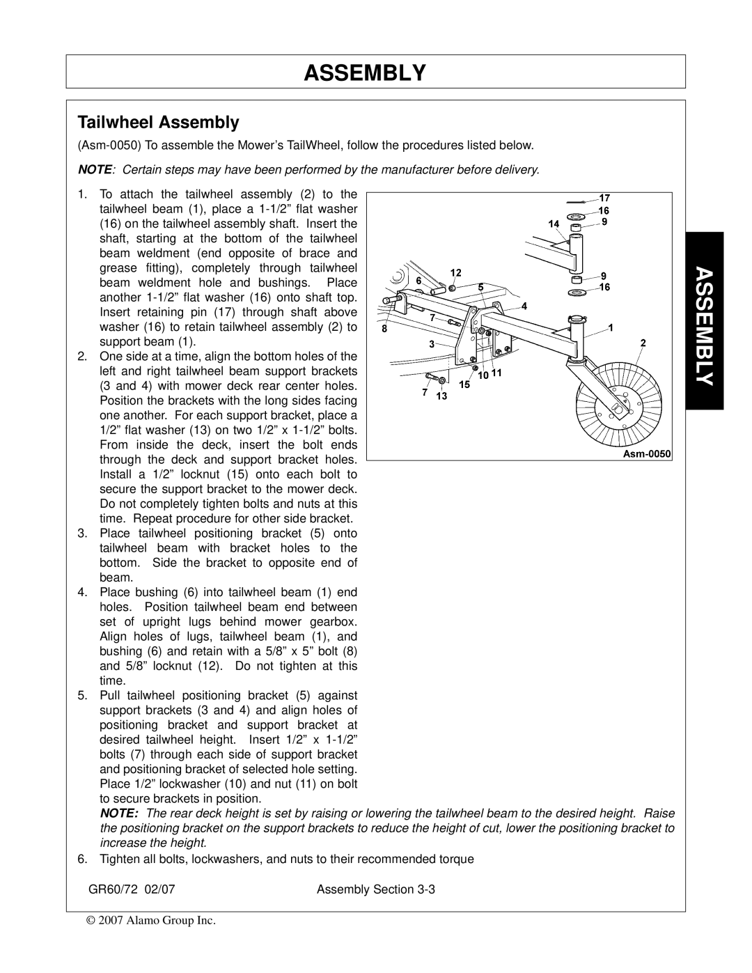
1.To attach the tailwheel assembly (2) to the tailwheel beam (1), place a
2.One side at a time, align the bottom holes of the left and right tailwheel beam support brackets (3 and 4) with mower deck rear center holes. Position the brackets with the long sides facing one another. For each support bracket, place a 1/2” flat washer (13) on two 1/2” x
3.Place tailwheel positioning bracket (5) onto tailwheel beam with bracket holes to the bottom. Side the bracket to opposite end of beam.
4.Place bushing (6) into tailwheel beam (1) end holes. Position tailwheel beam end between set of upright lugs behind mower gearbox. Align holes of lugs, tailwheel beam (1), and bushing (6) and retain with a 5/8” x 5” bolt (8) and 5/8” locknut (12). Do not tighten at this time.
5.Pull tailwheel positioning bracket (5) against support brackets (3 and 4) and align holes of positioning bracket and support bracket at desired tailwheel height. Insert 1/2” x
NOTE: The rear deck height is set by raising or lowering the tailwheel beam to the desired height. Raise the positioning bracket on the support brackets to reduce the height of cut, lower the positioning bracket to increase the height.
6.Tighten all bolts, lockwashers, and nuts to their recommended torque
GR60/72 02/07 | Assembly Section |
© 2007 Alamo Group Inc.
