ASSEMBLY
FRONT AND REAR DEFLECTORS (Standard Equipment) CHAINGUARDS ( OPTIONAL EQUIPMENT)
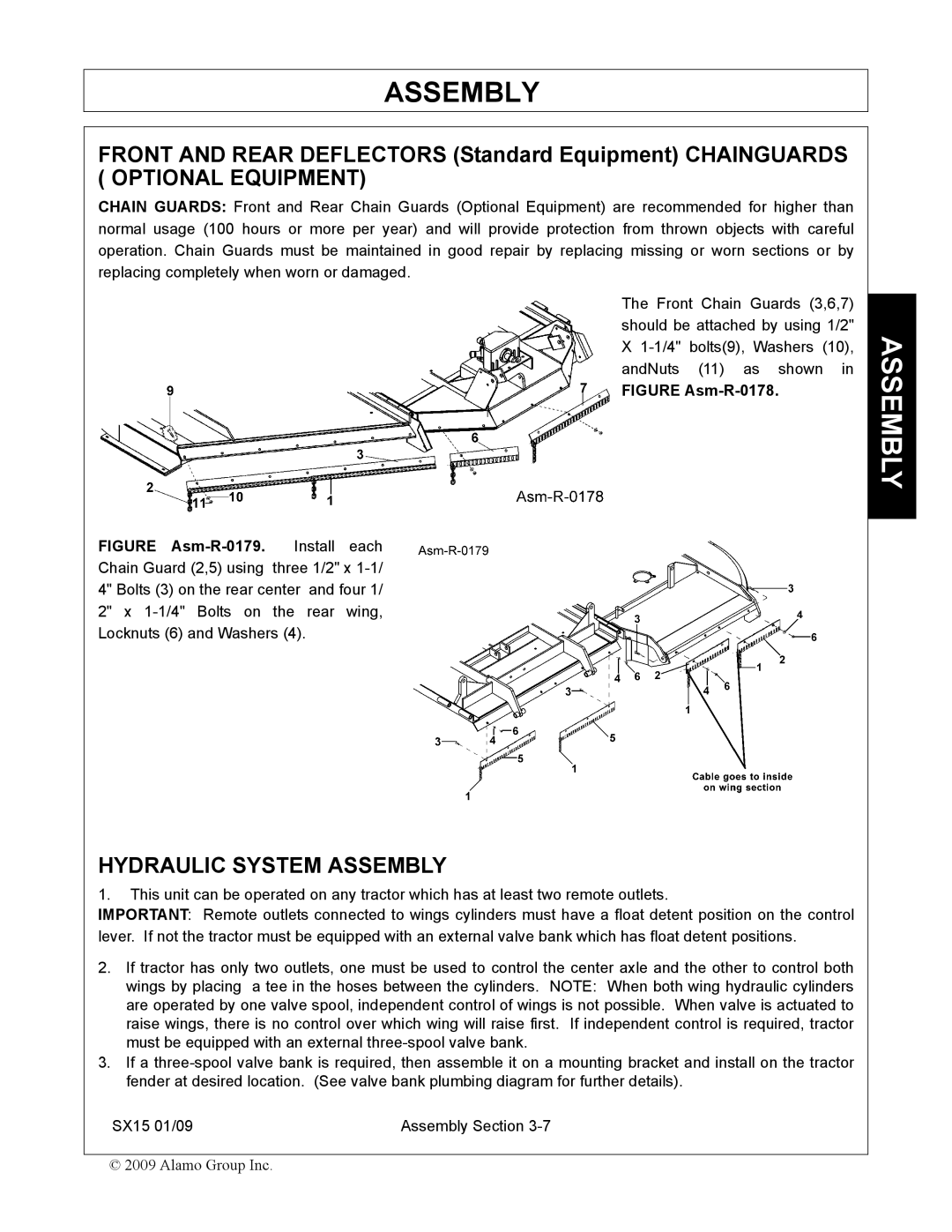
CHAIN GUARDS: Front and Rear Chain Guards (Optional Equipment) are recommended for higher than normal usage (100 hours or more per year) and will provide protection from thrown objects with careful operation. Chain Guards must be maintained in good repair by replacing missing or worn sections or by replacing completely when worn or damaged.
The Front Chain Guards (3,6,7) should be attached by using 1/2" X
FIGURE Asm-R-0178.
FIGURE Asm-R-0179. Install each
Chain Guard (2,5) using three 1/2" x
HYDRAULIC SYSTEM ASSEMBLY
1.This unit can be operated on any tractor which has at least two remote outlets.
IMPORTANT: Remote outlets connected to wings cylinders must have a float detent position on the control lever. If not the tractor must be equipped with an external valve bank which has float detent positions.
2.If tractor has only two outlets, one must be used to control the center axle and the other to control both wings by placing a tee in the hoses between the cylinders. NOTE: When both wing hydraulic cylinders are operated by one valve spool, independent control of wings is not possible. When valve is actuated to raise wings, there is no control over which wing will raise first. If independent control is required, tractor must be equipped with an external
3.If a
SX15 01/09 | Assembly Section |
© 2009 Alamo Group Inc.