Hardware Installation Guide
AVT Cameras
Legal notice
Allied Vision Technologies GmbH 03/2008
Contents
Control and video data signals
Camera interfaces Ieee 1394a port pin assignment
Contacting Allied Vision Technologies
Info Technical information
Ordering and commercial information
AVT Modular Camera Concept
Introduction
Document history
Manual overview
Conventions used in this manual
Styles
Read all notes and cautions carefully
Style Function Example
Symbols
AVT accessories
More information
Existing applications
Www For more information on accessories go to
AVT software
Packages
Www
AVT Technical Manuals
Www For downloading the Technical Manuals go to
Safety instructions
General safety instructions
FireWire safety instructions
Changing filters safety instructions
FireWire hot-plug and screw-lock precautions
Screw-lock precautions
Guppy changing filters safety instructions
PIKE/OSCAR changing filters safety instructions
Marlin changing filters safety instructions
PIKE/STINGRAY GOF connectors
PIKE/STINGRAY voltages
Guppy voltages
MARLIN/OSCAR voltages
Dolphin voltages
Safety instructions
Safety instructions for board level cameras
Ited warranty or cancelation of warranty
Tions before use
Always use clean boards
Board level cameras General Warnings
Board level cameras Loading
Board level cameras Dirty environments
AVT camera cleaning instructions
Warranty
Warranty precautions
General warnings
Avoiding the necessity of camera cleaning
Where is the impurity? Locating impurities
Is it an impurity? Identifying impurities
Camera type Tool to be used Description
Cleaning Instructions
Medical-grade sterile optical cotton
Scratches
Are not free from contamination
Iar with cleaning a camera with this instrument
AVT dealer
AVT cameras installing hardware
AVT SoftwarePackages
Hardware conditions
1394b for different requirements
FireWire cable Description
K1200165
Marlin / Oscar / Guppy
K1200162
Overview hardware installation
Installing Ieee 1394 adapter
Connecting camera to PC or laptop
Hot-plug precautions
Do not touch the shield of the camera cable con
Camera
Pin camera Connector Status LEDs
Ieee 1394b connector copper
Camera interfaces
Hirose and 1x 1394a
Hirose and 1x 1394a Hirose and 2x 1394b
Rear view of AVT cameras Hirose and 1394 copper
Pike fiber Stingray fiber
Pin Signal
Cable power
Ieee 1394a port pin assignment
Cable GND
Signal Pin
Board level camera Ieee 1394a port pin assignment
Cable shield
VP Power, VCC
Ieee 1394b port pin assignment PIKE, Stingray
Makes it possible to control the camera and output
Second camera
Power
PIKE/STINGRAY fiber infos and cautions
GOF transmission uses MMF multi-mode fiber at 850 nm
Optical connection ok
Plug clean
On the GOF connector
Sion
Please note that optical fiber cables have a
Pin Signal Direction Level Description
Camera I/O pin assignment 8 pin Guppy
Board level camera Guppy I/O pin assignment
Camera I/O connector pin assignment 12 pin
Order text Order number
K7600040
As shown below
Pin Signal Use
Dolphin family
Oscar and Marlin family
GPOutput Open emitter
Pike and Stingray family
Level Description
Control and video data signals
Technical Manuals
Inputs DOLPHIN, OSCAR, MARLIN, GUPPY, PIKE, Stingray
Guppy outputs are not short-circuit-proof
Input schematics Pike
Flux voltage from LED type 1.2 V at 20 mA
Input characteristics Flux voltage OSCAR, MARLIN, Pike
Cycle delay of the optical coupler
Flux voltage from LED type 1.5 V at 10 mA
Recommended Description Ratings Operating conditions
Guppy The inputs can be connected directly to +5
Voltages above +30 V may damage the optical coupler
ALL Cameras The following note is valid for all cameras
Registers see the Technical Manuals
Input Ground InGND Pin no from camera I/O connector Pike
Input Ground InGND Pin no from camera I/O connector Stingray
Outputs Dolphin
Parameter Test condition Value
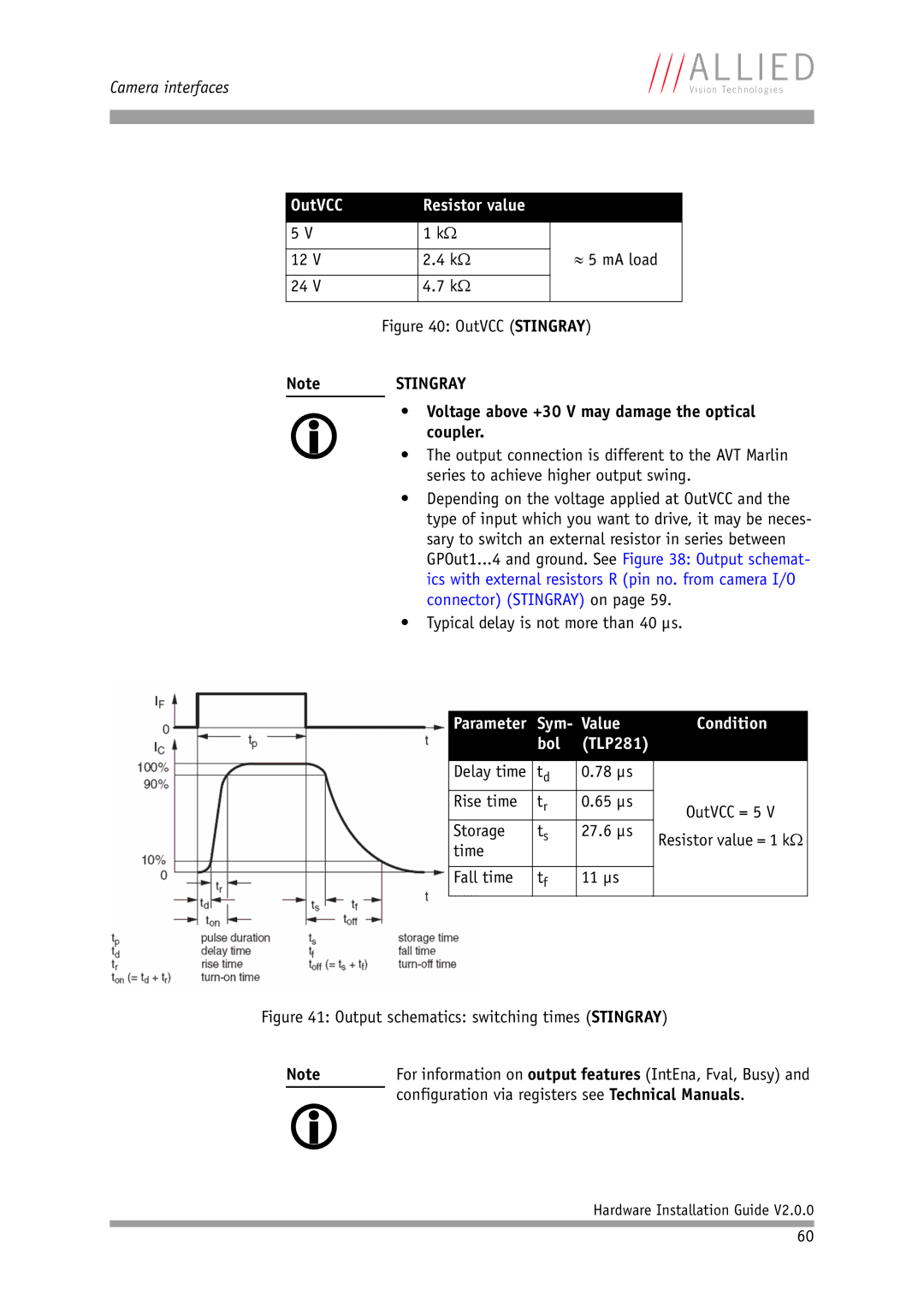
OutVCC Resistor value
See Output schematics with external resistor R Dolphin on
Configuration via registers see Technical Manuals
Outputs OSCAR/MARLIN
Emitter current Max mA Emitter collector voltage
Outputs Guppy
Outputs Operating conditions
Outputs Pike
Output parameters Pike
Voltage above +45 V may damage the optical coupler
Sym Value Condition Bol
00 µs Rise time 60 µs
Storage 48.00 µs
Outputs Stingray
Output parameters Stingray
≈ 5 mA load
Voltage above +30 V may damage the optical coupler
78 µs Rise time 65 µs
Storage 27.6 µs
Firmware update
Contact your local dealer
Index
Operating
Operating system
Optical coupler
40, 42