AT-8000S specifications
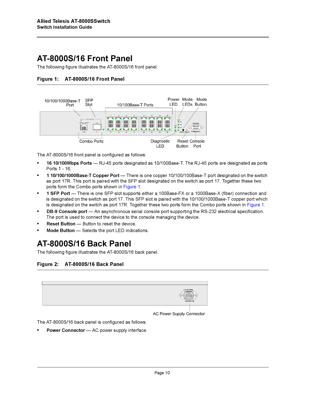
The Allied Telesis AT-8000S series switches are a range of advanced Layer 2 Ethernet switches designed for efficient networking in various environments. Engineered with performance, reliability, and cost-effectiveness in mind, these switches are ideal for businesses seeking to enhance their network infrastructure.One of the main features of the AT-8000S series is its high-speed data forwarding capabilities. With support for 10/100/1000 Mbps Ethernet ports, these switches provide fast and reliable connections, enabling seamless data transfer and enhanced communication between devices. The non-blocking switching architecture ensures that full bandwidth is available at all times, maximizing throughput and reducing latency in network traffic.
The AT-8000S series incorporates advanced Layer 2 switching technologies, such as VLAN support, allowing users to segment network traffic for improved performance and security. Virtual Local Area Networks (VLANs) help isolate sensitive data and reduce unnecessary broadcast traffic, enhancing the overall performance of the network.
Quality of Service (QoS) is another significant feature integrated into these switches, prioritizing different classes of network traffic. This functionality ensures that critical applications receive the necessary bandwidth and minimal latency, which is imperative for voice over IP, video conferencing, and other latency-sensitive applications.
In terms of network management, the AT-8000S series provides a variety of options, including an intuitive web-based interface, SNMP support, and the ability to manage switch configurations through console access. This flexibility allows network administrators to monitor performance and manage configurations easily.
The switches are built for durability, featuring a robust design suitable for deployment in various environments, including temperature-sensitive areas. Power over Ethernet (PoE) capability is also available in certain models, allowing network devices like IP cameras and wireless access points to receive power through the same cable as data, simplifying installation and reducing clutter.
Allied Telesis emphasizes security within the AT-8000S series, with features such as port security, DHCP snooping, and IEEE 802.1X authentication to safeguard against unauthorized access and potential threats.
Overall, the Allied Telesis AT-8000S series provides a comprehensive networking solution tailored for modern business needs, combining performance, flexibility, and security to support a growing array of applications and devices within the network.

