5.Change the password.
Change the password as soon as possible because a manager account with the default password is a serious security risk. Remember the new password because there is no way to retrieve it if you forget it.
To change the account password, use the set password command.
6.Display help for commands as necessary.
To display a list of help topics, use the help command.
To display help on a specific topic, use the help <topic> command.
Alternatively, display a list of valid options by typing a question mark at the end of a partial command.
Checking LEDs
Table 1 describes how LEDs on the switch report faults and operational activities.
Table 2 on page 14 describes how LEDs on power supply units and
LEDs for Ethernet ports and Small Form Factor Pluggable (SFP) ports are described in the Hardware Reference.
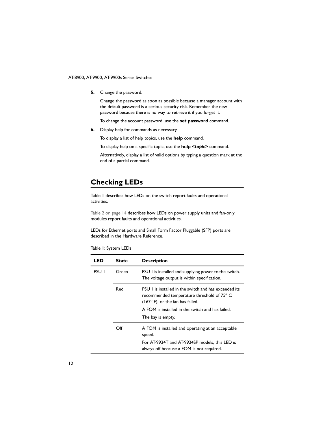
Table 1: System LEDs
LED | State | Description |
|
|
|
PSU 1 | Green | PSU 1 is installed and supplying power to the switch. |
|
| The voltage output is within specification. |
|
|
|
| Red | PSU 1 is installed in the switch and has exceeded its |
|
| recommended temperature threshold of 75º C |
|
| (167º F), or the fan has failed. |
|
| A FOM is installed in the switch and has failed. |
|
| The bay is empty. |
|
|
|
| Off | A FOM is installed and operating at an acceptable |
|
| speed. |
|
| For |
|
| always off because a FOM is not required. |
|
|
|
12