Collapsed Backbone
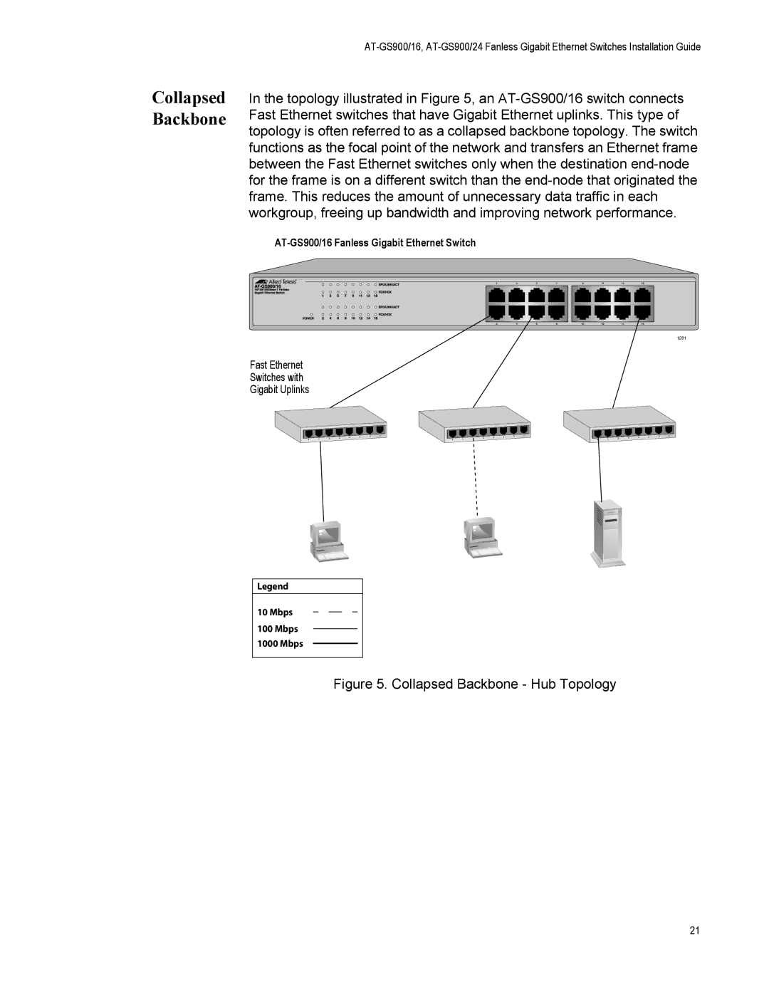
In the topology illustrated in Figure 5, an
1281
Fast Ethernet
Switches with
Gigabit Uplinks
|
|
| 5 | 4 | 3 | 2 | 1 |
|
|
| 5 | 4 | 3 | 2 | 1 |
|
|
| 5 | 4 | 3 | 2 | 1 |
8 | 7 | 6 |
|
| 8 | 7 | 6 |
|
| 8 | 7 | 6 |
|
| |||||||||
|
|
|
|
|
|
|
|
|
|
|
|
|
|
|
Legend
10 Mbps
100Mbps 1000 Mbps
Figure 5. Collapsed Backbone - Hub Topology
21
In the topology illustrated in Figure 5, an
1281
Fast Ethernet
Switches with
Gigabit Uplinks
|
|
| 5 | 4 | 3 | 2 | 1 |
|
|
| 5 | 4 | 3 | 2 | 1 |
|
|
| 5 | 4 | 3 | 2 | 1 |
8 | 7 | 6 |
|
| 8 | 7 | 6 |
|
| 8 | 7 | 6 |
|
| |||||||||
|
|
|
|
|
|
|
|
|
|
|
|
|
|
|
Legend
10 Mbps
100Mbps 1000 Mbps
21