Chapter 2: Installation
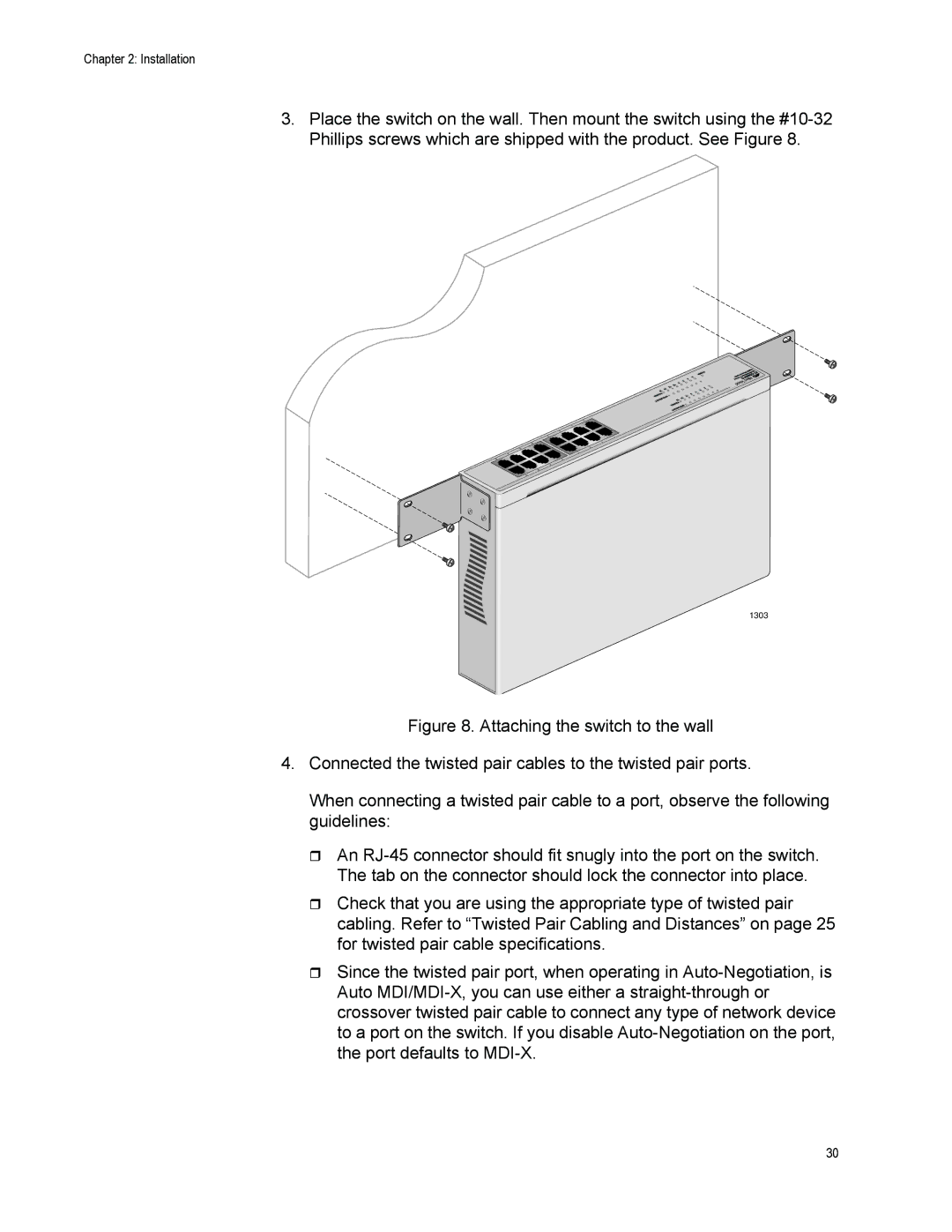
3.Place the switch on the wall. Then mount the switch using the
1303
Figure 8. Attaching the switch to the wall
4.Connected the twisted pair cables to the twisted pair ports.
When connecting a twisted pair cable to a port, observe the following guidelines:
An RJ-45 connector should fit snugly into the port on the switch. The tab on the connector should lock the connector into place.
Check that you are using the appropriate type of twisted pair cabling. Refer to “Twisted Pair Cabling and Distances” on page 25 for twisted pair cable specifications.
Since the twisted pair port, when operating in Auto-Negotiation, is Auto MDI/MDI-X, you can use either a straight-through or crossover twisted pair cable to connect any type of network device to a port on the switch. If you disable Auto-Negotiation on the port, the port defaults to MDI-X.
30