Cabling the Switch
To connect to the ports on the
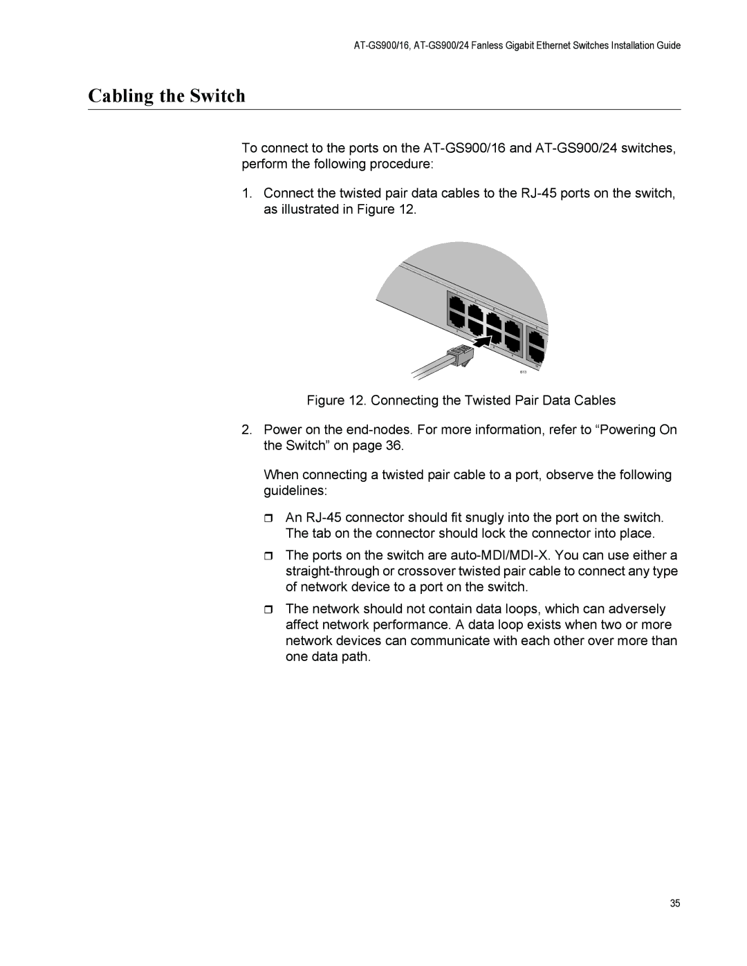
1.Connect the twisted pair data cables to the
613
Figure 12. Connecting the Twisted Pair Data Cables
2.Power on the end-nodes. For more information, refer to “Powering On the Switch” on page 36.
When connecting a twisted pair cable to a port, observe the following guidelines:
An RJ-45 connector should fit snugly into the port on the switch. The tab on the connector should lock the connector into place.
The ports on the switch are auto-MDI/MDI-X. You can use either a straight-through or crossover twisted pair cable to connect any type of network device to a port on the switch.
The network should not contain data loops, which can adversely affect network performance. A data loop exists when two or more network devices can communicate with each other over more than one data path.
35