Chapter 1: Overview
x600-48Ts/XP Switch
The
44
Four Gigabit Ethernet small
Two 10 Gigabit Ethernet small form factor pluggable (XFP) transceiver slots
An
One SD slot supporting 512KB and 1GB SD cards
Status LEDs for the ports, transceiver slots, and system
Redundant power supply connector
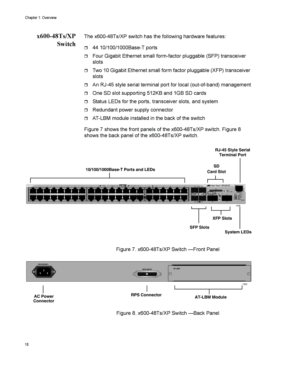
Figure 7 shows the front panels of the x600-48Ts/XP switch. Figure 8 shows the back panel of the x600-48Ts/XP switch.
|
| ||||
|
|
| Terminal Port | ||
|
|
| |||
SD |
| ||||
Card Slot |
| ||||
|
|
| |||
|
|
|
|
|
|
|
|
|
|
|
|
|
|
|
|
|
|
|
|
|
|
|
|
|
|
|
|
|
|
|
|
|
|
|
| L/A |
|
| D/C |
|
|
|
|
|
|
|
|
|
|
|
|
|
|
|
|
|
|
|
| L/A | 1000 LINK / ACT | 10/100 LINK / | ACT |
|
| D/C FDX | HDX / | COL |
|
|
|
|
|
|
|
| |
1 | 3 | 5 | 7 | 9 | 11 | 13 | 15 | 17 | 19 | 21 | 23 | 25 |
|
| 27 | 29 | 31 | 33 |
| 35 | 37 | 39 | 41 | 43 | ||
|
|
|
|
|
|
|
|
|
|
|
|
|
|
|
|
|
|
|
|
|
|
|
|
|
|
|
|
|
|
|
|
|
|
|
|
|
|
|
|
|
|
|
|
|
|
|
|
|
|
|
|
|
|
|
|
|
|
|
|
|
|
|
|
|
|
|
| SFP Slots |
|
|
|
|
| ||
|
|
|
|
|
|
|
|
|
|
|
|
|
|
|
|
|
|
|
|
|
|
2 | 4 | 6 | 8 | 10 | 12 | 14 | 16 | 18 | 20 | 22 | 24 | 26 | 28 | 30 | 32 | 34 | 36 | 38 | 40 | 42 | 44 |
|
|
|
|
|
|
|
|
45 | SFP | 47 |
| Layer 3 Gigabit Ethernet Switch |
|
| |
|
|
| SD |
|
|
|
|
|
|
|
| READY |
|
|
|
|
|
|
| BUSY | FAULT | CONSOLE | |
|
|
| CLASS 1 |
|
| ||
|
|
| LASER PRODUCT |
|
|
|
|
|
|
| LINK / | ACT |
| STACK | STATUS |
|
|
| XFP | XFP |
| MSTR | FAULT |
|
|
| L/A |
|
| ||
|
|
|
|
| 1 | L/A | MASTER |
|
|
|
|
| 2 | L/A | RPS |
|
|
|
|
|
| PRES | PWR |
|
|
|
|
|
|
| RESET |
46 | L/A | 48 | 49 | 50 |
|
|
|
1308
XFP Slots
SFP Slots
System LEDs
Figure 7. x600-48Ts/XP Switch —Front Panel
RPS INPUT |
1309
|
|
|
|
|
| |
|
|
|
|
|
| |
|
| RPS Connector |
|
| ||
AC Power | ||||||
|
| |||||
Connector
Figure 8. x600-48Ts/XP Switch —Back Panel
18