x600 Series Layer 3 Gigabit Ethernet Switches Installation Guide
System LEDs
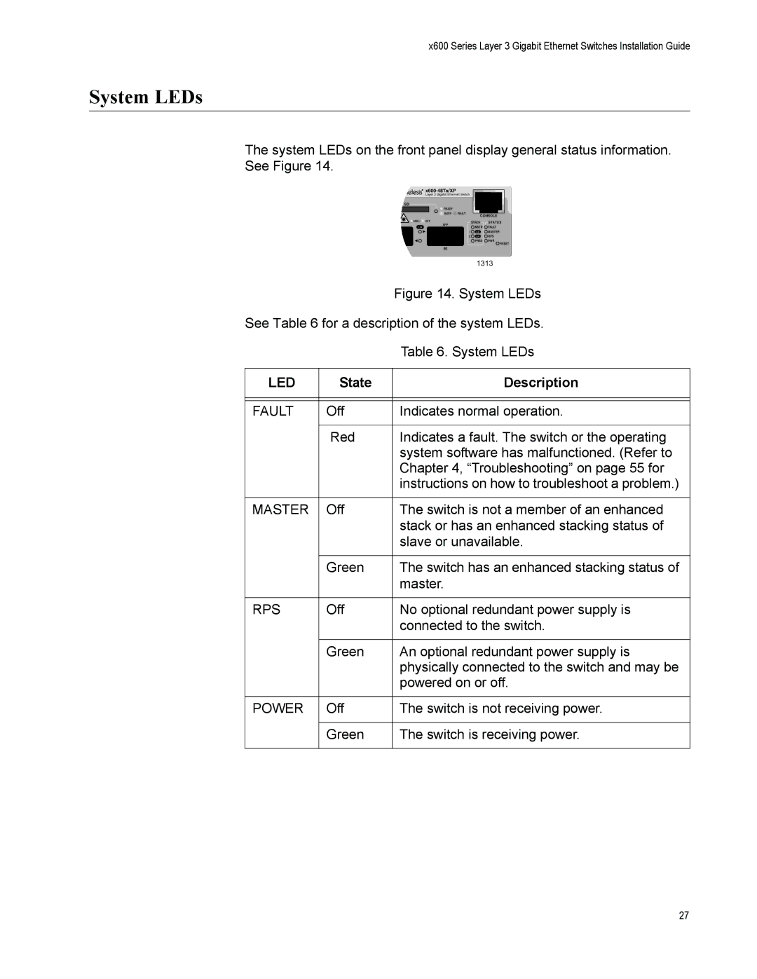
The system LEDs on the front panel display general status information.
See Figure 14.

x600-48Ts/XP
Layer 3 Gigabit Ethernet Switch
SD
![]() READY
READY
BUSY FAULT
CONSOLE
LINK / ACT | STACK | STATU S |
XFP | MSTR | FAULT |
L/A | ||
1 | L/A | MASTER |
2 | L/A | RPS |
| PRES | PWR |
|
| RESET |
50
1313
Figure 14. System LEDs
See Table 6 for a description of the system LEDs.
|
| Table 6. System LEDs |
|
|
|
LED | State | Description |
|
|
|
|
|
|
FAULT | Off | Indicates normal operation. |
|
|
|
| Red | Indicates a fault. The switch or the operating |
|
| system software has malfunctioned. (Refer to |
|
| Chapter 4, “Troubleshooting” on page 55 for |
|
| instructions on how to troubleshoot a problem.) |
|
|
|
MASTER | Off | The switch is not a member of an enhanced |
|
| stack or has an enhanced stacking status of |
|
| slave or unavailable. |
|
|
|
| Green | The switch has an enhanced stacking status of |
|
| master. |
|
|
|
RPS | Off | No optional redundant power supply is |
|
| connected to the switch. |
|
|
|
| Green | An optional redundant power supply is |
|
| physically connected to the switch and may be |
|
| powered on or off. |
|
|
|
POWER | Off | The switch is not receiving power. |
|
|
|
| Green | The switch is receiving power. |
|
|
|
27