INSTALLATION EXAMPLES (CONT'D)
Example diagram
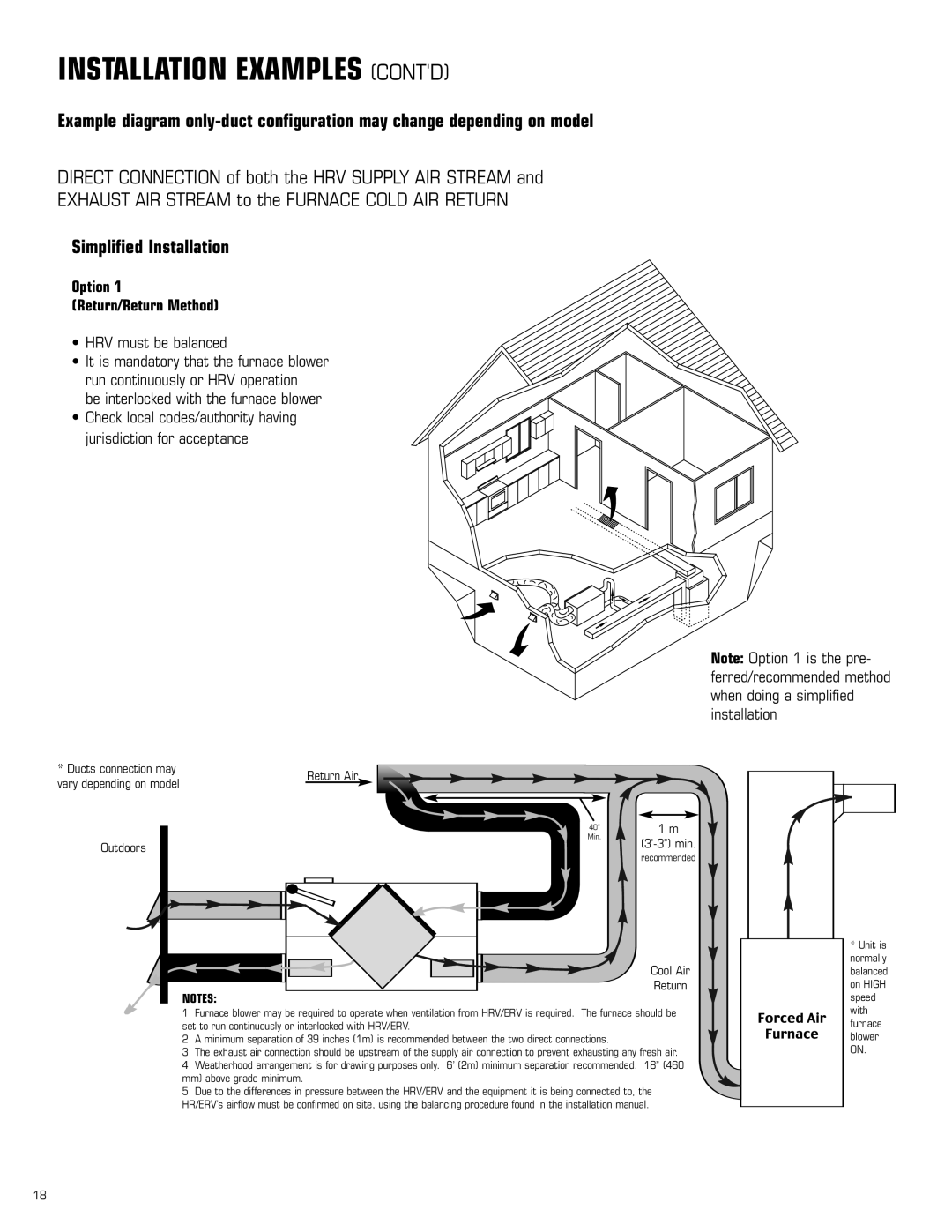
DIRECT CONNECTION of both the HRV SUPPLY AIR STREAM and
EXHAUST AIR STREAM to the FURNACE COLD AIR RETURN
Simplified Installation
Option 1
(Return/Return Method)
• HRV must be balanced
• It is mandatory that the furnace blower run continuously or HRV operation
be interlocked with the furnace blower
• Check local codes/authority having jurisdiction for acceptance
Note: Option 1 is the pre- ferred/recommended method when doing a simplified installation
* Ducts connection may | Return Air |
|
vary depending on model |
| |
|
| |
| 40” | 1 m |
Outdoors | Min. | |
| ||
| recommended | |
|
| |
|
| Cool Air |
| NOTES: | Return |
|
|
1.Furnace blower may be required to operate when ventilation from HRV/ERV is required. The furnace should be set to run continuously or interlocked with HRV/ERV.
2.A minimum separation of 39 inches (1m) is recommended between the two direct connections.
3.The exhaust air connection should be upstream of the supply air connection to prevent exhausting any fresh air.
4.Weatherhood arrangement is for drawing purposes only. 6’ (2m) minimum separation recommended. 18” (460 mm) above grade minimum.
5.Due to the differences in pressure between the HRV/ERV and the equipment it is being connected to, the HR/ERV’s airflow must be confirmed on site, using the balancing procedure found in the installation manual.
*Unit is normally balanced on HIGH speed with furnace blower ON.
18