INSTALLATION EXAMPLES (CONT'D)
Example diagram
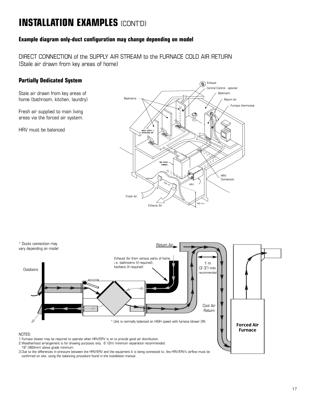
DIRECT CONNECTION of the SUPPLY AIR STREAM to the FURNACE COLD AIR RETURN (Stale air drawn from key areas of home)
Partially Dedicated System
Stale air drawn from key areas of home (bathroom, kitchen, laundry)
Fresh air supplied to main living areas via the forced air system.
HRV must be balanced
Bedrooms
1800 | mm |
|
Fresh Air
Exhaust ![]() A
A![]() ir
ir
Exhaust
Central Control - optional
Bathroom
Return Air
Fu![]() rnace
rnace ![]() the
the![]() rmostat
rmostat
HRV
Connection
![]() HRV
HRV![]()
![]() 460 mm
460 mm
*Ducts connection may vary depending on model
Outdoors
Return Air
Exhaust Air from various parts of home. i.e. bathrooms (if required),
kitchens (if required)
1 m
recommended
Cool Air
Return
* Unit is normally balanced on HIGH speed with furnace blower ON.
NOTES:
1.Furnace blower may be required to operate when HRV/ERV is on to provide good air distribution. 2.Weatherhood arrangement is for drawing purposes only. 6’ (2m) minimum separation recommended.
18” (460mm) above grade minimum.
3.Due to the differences in pressure between the HRV/ERV and the equipment it is being connected to, the HRV/ERV’s airflow must be confirmed on site, using the balancing procedure found in the installation manual.
17