AIR FLOW BALANCING (CONT'D)
AIRFLOW STATION (GRID) METHOD
B
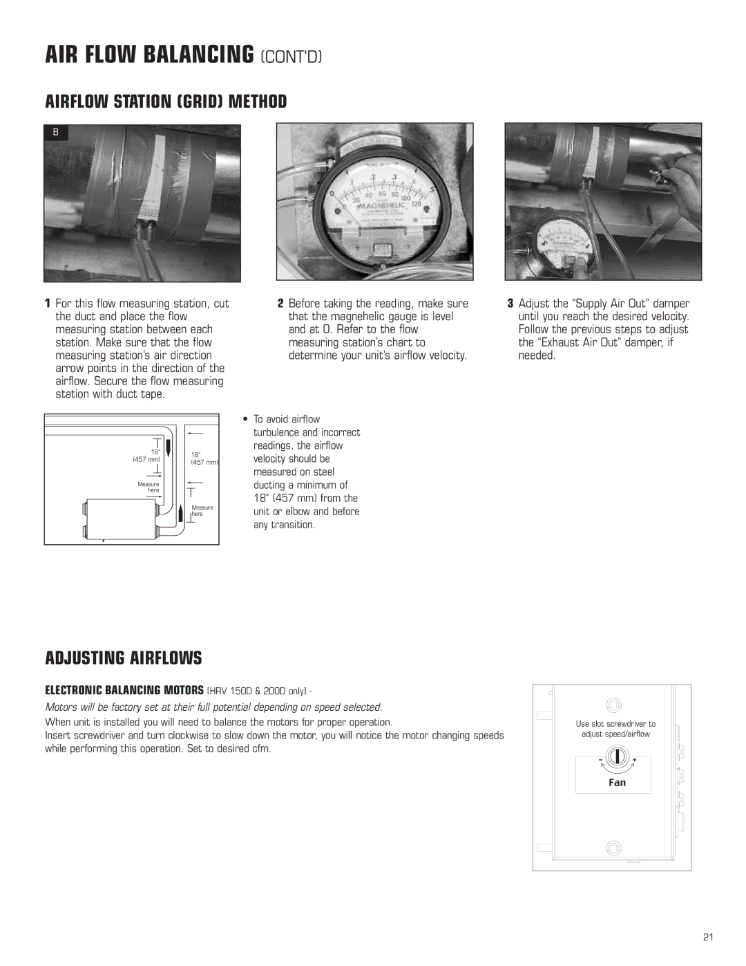
1For this flow measuring station, cut the duct and place the flow measuring station between each station. Make sure that the flow measuring station’s air direction arrow points in the direction of the airflow. Secure the flow measuring station with duct tape.
2Before taking the reading, make sure that the magnehelic gauge is level and at 0. Refer to the flow measuring station’s chart to determine your unit’s airflow velocity.
3Adjust the “Supply Air Out” damper until you reach the desired velocity. Follow the previous steps to adjust the “Exhaust Air Out” damper, if needed.
18” | 18” | |
(457 mm) | ||
(457 mm) | ||
| ||
Measure |
| |
here |
| |
| Measure | |
| here |
•To avoid airflow turbulence and incorrect readings, the airflow velocity should be measured on steel ducting a minimum of 18” (457 mm) from the unit or elbow and before any transition.
ADJUSTING AIRFLOWS
ELECTRONIC BALANCING MOTORS [HRV 150D & 200D only] -
Motors will be factory set at their full potential depending on speed selected.
When unit is installed you will need to balance the motors for proper operation.
Insert screwdriver and turn clockwise to slow down the motor, you will notice the motor changing speeds while performing this operation. Set to desired cfm.
Use slot screwdriver to | |
adjust speed/airflow | |
- | + |
| Fan |
21