3.Piping Connections
ALL components/materials must conform to National Fuel Gas Code Specifications ANSI Z223.1-LATEST EDITION, or in Canada, CAN/CGA-B149.1-M91 (Natural Gas) or CAN/CGA-B149.2-M91 (Liquid Propane [L.P.] Gas) or LATEST EDITION (for General Installation and Gas Plumbing), as well as local codes and ordinances and must be done by a qualified professional. It is important that gas pressure regulators meet applicable pressure requirements, and that gas meters be rated for the total amount of ALL the appliance BTUs being supplied.
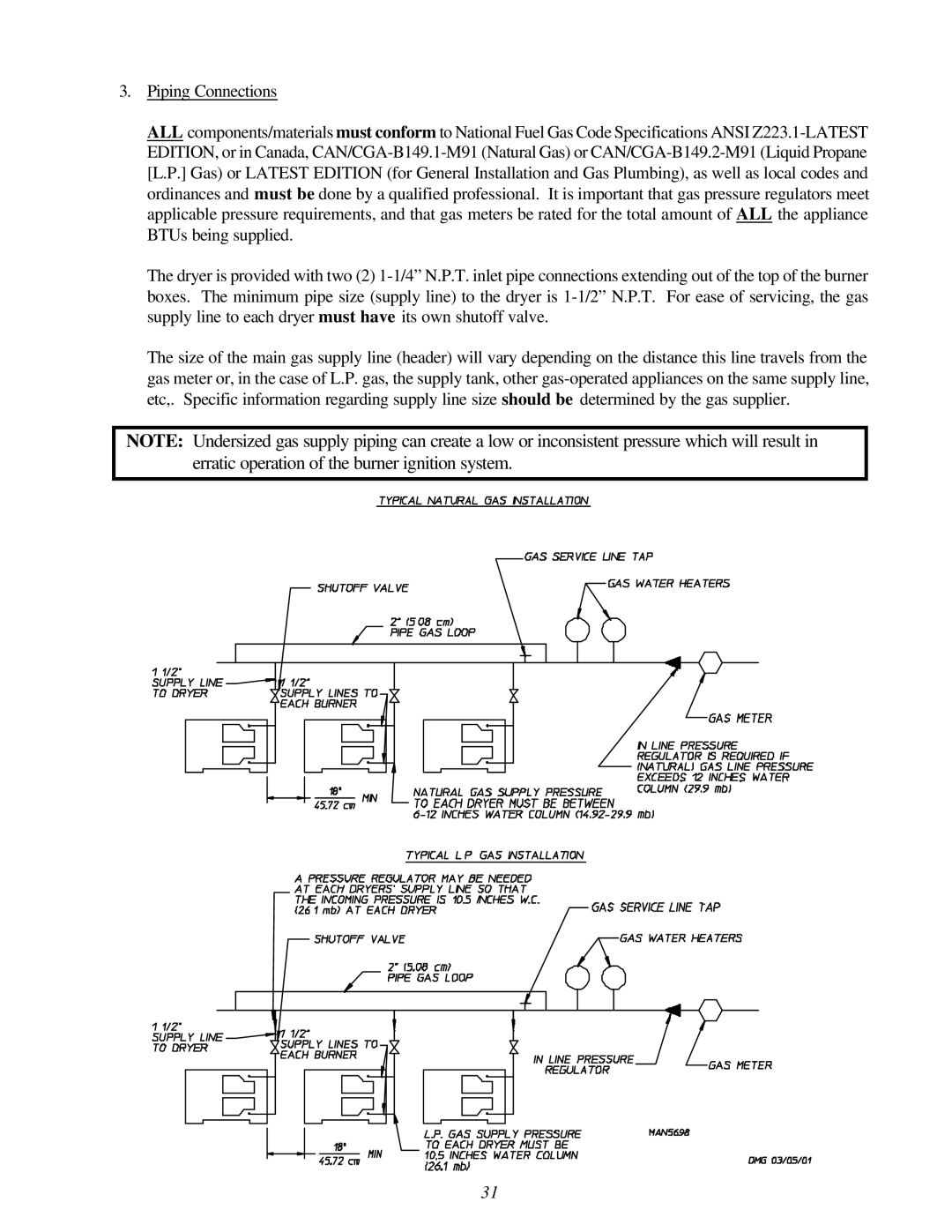
The dryer is provided with two (2) 1-1/4” N.P.T. inlet pipe connections extending out of the top of the burner boxes. The minimum pipe size (supply line) to the dryer is 1-1/2” N.P.T. For ease of servicing, the gas supply line to each dryer must have its own shutoff valve.
The size of the main gas supply line (header) will vary depending on the distance this line travels from the gas meter or, in the case of L.P. gas, the supply tank, other gas-operated appliances on the same supply line, etc,. Specific information regarding supply line size should be determined by the gas supplier.
NOTE: Undersized gas supply piping can create a low or inconsistent pressure which will result in erratic operation of the burner ignition system.