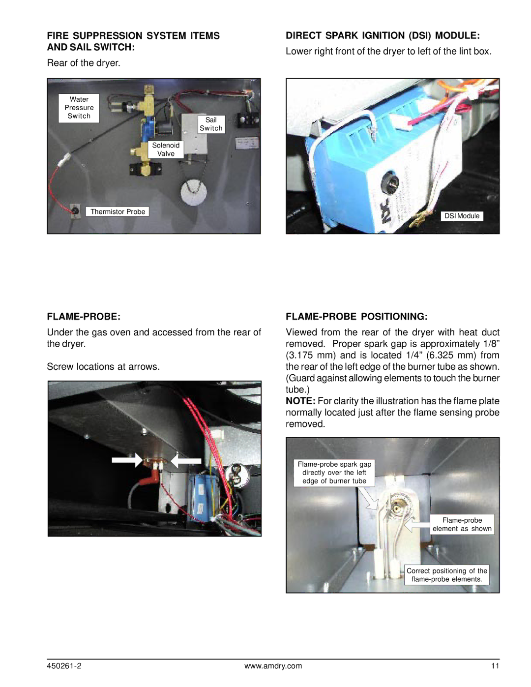
FIRE SUPPRESSION SYSTEM ITEMS AND SAIL SWITCH:
Rear of the dryer.
Water
Pressure
Switch
Sail
Switch
Solenoid
Valve
Thermistor Probe
DIRECT SPARK IGNITION (DSI) MODULE:
Lower right front of the dryer to left of the lint box.
DSI Module
FLAME-PROBE:
Under the gas oven and accessed from the rear of the dryer.
Screw locations at arrows.
FLAME-PROBE POSITIONING:
Viewed from the rear of the dryer with heat duct removed. Proper spark gap is approximately 1/8” (3.175 mm) and is located 1/4” (6.325 mm) from the rear of the left edge of the burner tube as shown. (Guard against allowing elements to touch the burner tube.)
NOTE: For clarity the illustration has the flame plate normally located just after the flame sensing probe removed.
element as shown
Correct positioning of the
www.amdry.com | 11 |