Step 6 Attach Cables
Connectors The Apollo IV motherboard includes many connectors. Connection instructions, illustrations of connectors, and pinouts are:
Connector
Power supply connector
Keyboard connector
Mouse connector
CPU Fan
Chassis Fan
Infrared
Remote Power connector
USB connectors
Speaker
IDE LED
Remote Power Switch
Hardware Reset Switch
Power LED (lit when power is on)
Keyboard Lock
Turbo LED (lit when high speed is active)
Suspend Mode Switch
Suspend LED (lit when system in suspend mode)
Serial Port
Parallel port
Floppy drive connector
IDE drive connectors
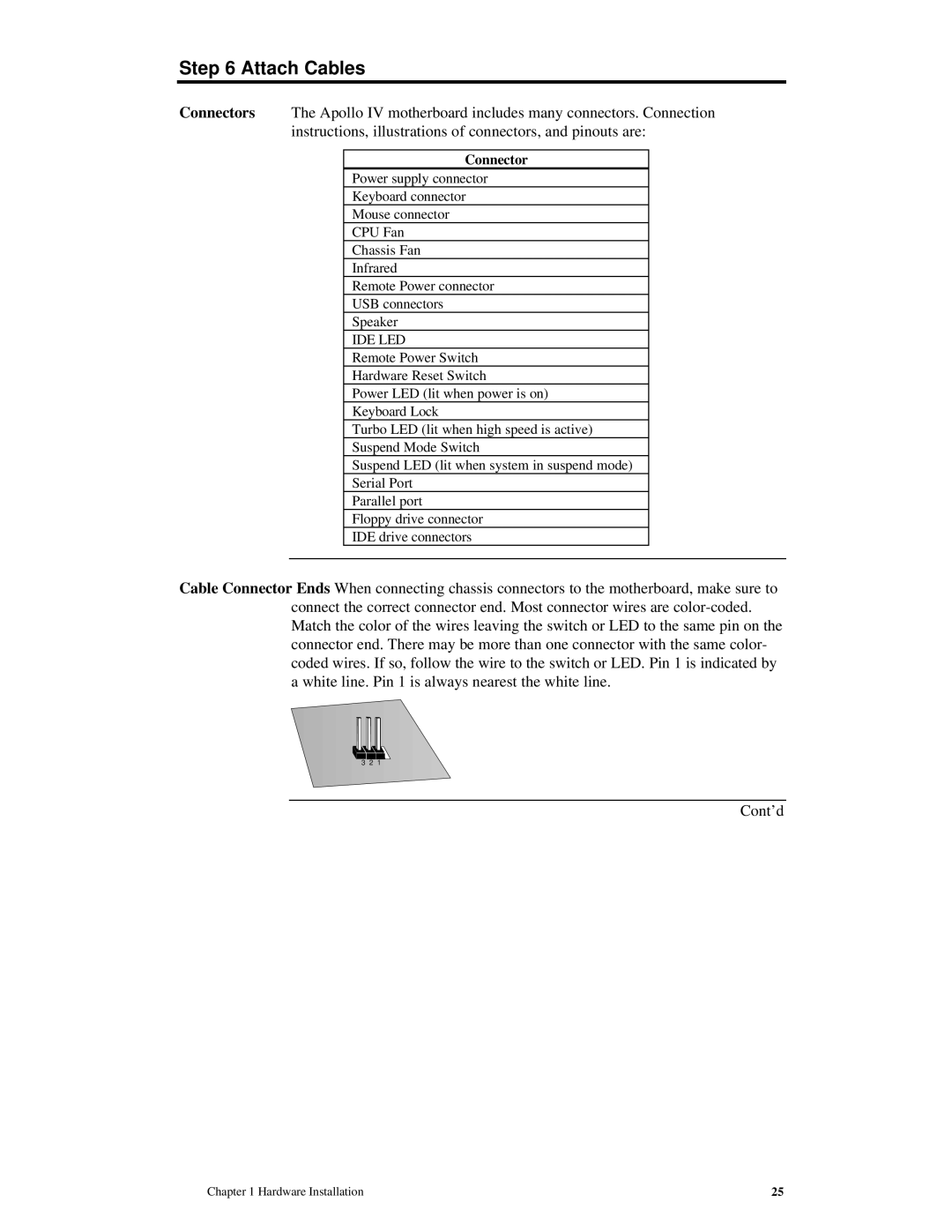
Cable Connector Ends When connecting chassis connectors to the motherboard, make sure to connect the correct connector end. Most connector wires are
3 2 1
Cont’d
Chapter 1 Hardware Installation | 25 |