3: OPERATION
INDICATORS AND CONTROLS ON THE
The APC Uninterruptible Power Supply (UPS) is designed to prevent blackouts, brownouts, sags and surges from reaching your computer and other valuable electronic equipment. The UPS filters out small utility line fluctuations and isolates your equipment from large disturbances by internally dis- connecting from the utility line. The UPS provides continuous power from its internal batteries until the utility line returns to safe levels.
The
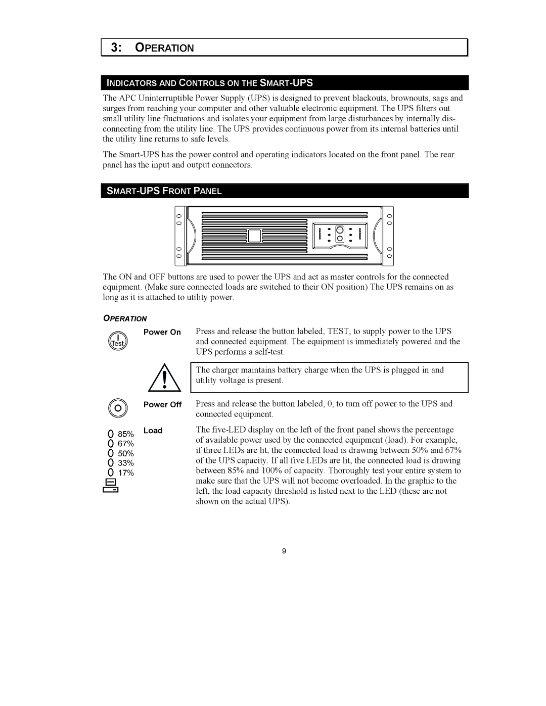
The ON and OFF buttons are used to power the UPS and act as master controls for the connected equipment. (Make sure connected loads are switched to their ON position) The UPS remains on as long as it is attached to utility power.
OPERATION
Power On
Power Off
Load
Press and release the button labeled, TEST, to supply power to the UPS and connected equipment. The equipment is immediately powered and the UPS performs a
The charger maintains battery charge when the UPS is plugged in and utility voltage is present.
Press and release the button labeled, 0, to turn off power to the UPS and connected equipment.
The
9