CONNECTING THE BATTERY AND ATTACHING THE FRONT BEZEL
|
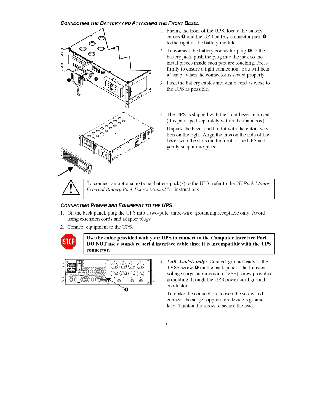
| 1. | Facing the front of the UPS, locate the battery | |
|
|
| cables Œ and the UPS battery connector jack • | |
|
|
| to the right of the battery module. | |
|
| 2. | To connect the battery connector plug Ž to the | |
|
|
| battery jack, push the plug into the jack so the | |
|
|
| metal pieces inside each part are touching. Press | |
|
| • | firmly to ensure a tight connection. You will hear | |
|
| a “snap” when the connector is seated properly. | ||
| Ž |
| ||
Π| 3. | Push the battery cables and white cord as close to | ||
| ||||
|
| |||
|
|
| the UPS as possible. | |
|
| 4. | The UPS is shipped with the front bezel removed | |
|
|
| (it is packaged separately within the main box). |
Unpack the bezel and hold it with the cutout sec- tion on the right. Align the tabs on the side of the bezel with the slots on the front of the UPS and gently snap it into place.
To connect an optional external battery pack(s) to the UPS, refer to the 3U Rack Mount External Battery Pack User’s Manual for instructions.
CONNECTING POWER AND EQUIPMENT TO THE UPS
1.On the back panel, plug the UPS into a
2.Connect equipment to the UPS.
Use the cable provided with your UPS to connect to the Computer Interface Port. DO NOT use a standard serial interface cable since it is incompatible with the UPS connector.
3. 120V Models only: Connect ground leads to the TVSS screw Πon the back panel. The transient voltage surge suppression (TVSS) screw provides grounding through the UPS power cord ground conductor.
Œ
To make the connection, loosen the screw and connect the surge suppression device’s ground lead. Tighten the screw to secure the lead.
7
