Configuration
Supported | Two supported configurations for Redundant Switch are shown |
configurations | below. For more information on these and other supported |
| configurations, visit the APC Web site at www.apc.com. |
|
| Install only SNMP accessories in the UPS. You |
|
| must install any other accessories in the |
|
| Redundant Switch |
| Note | Both UPSs must be the same |
|
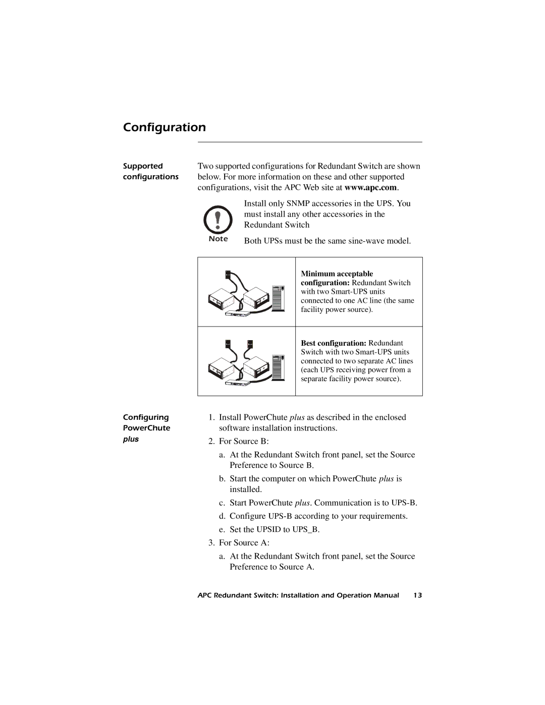
| Minimum acceptable |
|
| configuration: Redundant Switch |
|
| with two |
|
| connected to one AC line (the same |
|
| facility power source). |
|
| Best configuration: Redundant |
|
| Switch with two |
|
| connected to two separate AC lines |
|
| (each UPS receiving power from a |
|
| separate facility power source). |
Configuring | 1. Install PowerChute plus as described in the enclosed | |
PowerChute | software installation instructions. | |
plus | 2. For Source B: | |
a.At the Redundant Switch front panel, set the Source Preference to Source B.
b.Start the computer on which PowerChute plus is installed.
c.Start PowerChute plus. Communication is to
d.Configure
e.Set the UPSID to UPS_B.
3.For Source A:
a.At the Redundant Switch front panel, set the Source Preference to Source A.
APC Redundant Switch: Installation and Operation Manual | 13 |