Fig. 15 | Unit #1 |
| |
| T O P |
SENSOR |
|
WIRE | 6 |
|
10
7
| Unit #2 |
13 | T O P |
| |
SENSOR |
|
WIRE | 6 |
|
10
7
| Unit #3 |
13 | T O P |
| |
SENSOR |
|
WIRE | 6 |
|
10
7
8
12
8
12
8
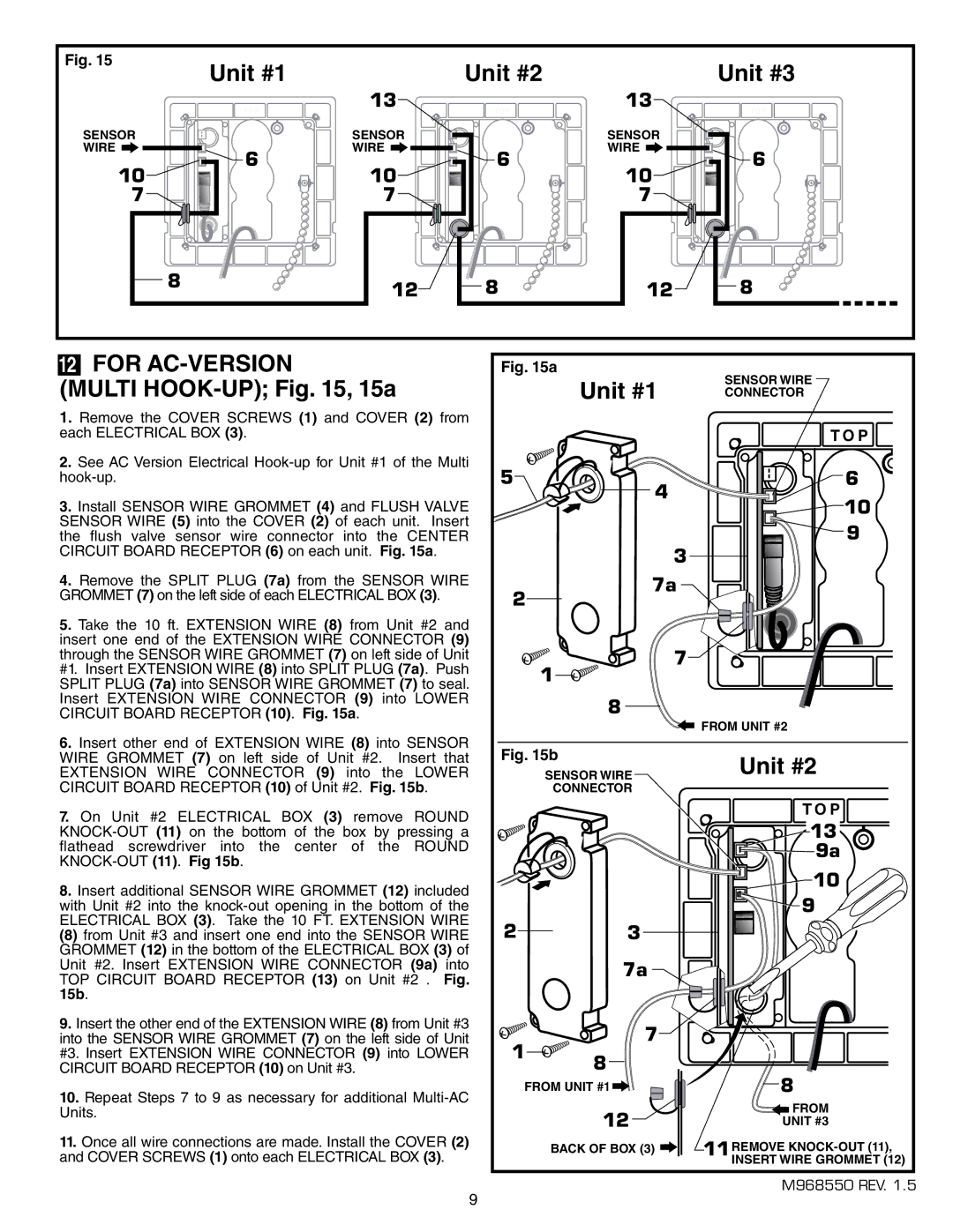
12FOR AC-VERSION
(MULTI HOOK-UP); Fig. 15, 15a
1. Remove the COVER SCREWS (1) and COVER (2) from each ELECTRICAL BOX (3).
2. See AC Version Electrical |
3. Install SENSOR WIRE GROMMET (4) and FLUSH VALVE |
SENSOR WIRE (5) into the COVER (2) of each unit. Insert |
the flush valve sensor wire connector into the CENTER |
CIRCUIT BOARD RECEPTOR (6) on each unit. Fig. 15a. |
Fig. 15a
Unit #1 | SENSOR WIRE |
CONNECTOR |
|
| T O P |
5 | 4 | 6 |
| 10 | |
|
| |
|
| 9 |
|
| 3 |
4. Remove the SPLIT PLUG (7a) from the SENSOR WIRE |
GROMMET (7) on the left side of each ELECTRICAL BOX (3). |
2
7a
5. Take the 10 ft. EXTENSION WIRE (8) from Unit #2 and |
insert one end of the EXTENSION WIRE CONNECTOR (9) |
through the SENSOR WIRE GROMMET (7) on left side of Unit |
#1. Insert EXTENSION WIRE (8) into SPLIT PLUG (7a). Push |
SPLIT PLUG (7a) into SENSOR WIRE GROMMET (7) to seal. |
Insert EXTENSION WIRE CONNECTOR (9) into LOWER |
CIRCUIT BOARD RECEPTOR (10). Fig. 15a. |
6. Insert other end of EXTENSION WIRE (8) into SENSOR |
WIRE GROMMET (7) on left side of Unit #2. Insert that |
EXTENSION WIRE CONNECTOR (9) into the LOWER |
CIRCUIT BOARD RECEPTOR (10) of Unit #2. Fig. 15b. |
7. On Unit #2 ELECTRICAL BOX (3) remove ROUND |
flathead screwdriver into the center of the ROUND |
8. Insert additional SENSOR WIRE GROMMET (12) included |
with Unit #2 into the |
ELECTRICAL BOX (3). Take the 10 FT. EXTENSION WIRE |
(8) from Unit #3 and insert one end into the SENSOR WIRE |
GROMMET (12) in the bottom of the ELECTRICAL BOX (3) of |
Unit #2. Insert EXTENSION WIRE CONNECTOR (9a) into |
TOP CIRCUIT BOARD RECEPTOR (13) on Unit #2 . Fig. |
15b. |
9. Insert the other end of the EXTENSION WIRE (8) from Unit #3 |
into the SENSOR WIRE GROMMET (7) on the left side of Unit |
#3. Insert EXTENSION WIRE CONNECTOR (9) into LOWER |
CIRCUIT BOARD RECEPTOR (10) on Unit #3. |
10. Repeat Steps 7 to 9 as necessary for additional |
Units. |
11. Once all wire connections are made. Install the COVER (2) |
and COVER SCREWS (1) onto each ELECTRICAL BOX (3). |
![]()
![]()
![]()
![]()
![]()
![]() 7
7![]() 1
1![]()
![]()
![]()
![]()
![]()
![]()
8
![]() FROM UNIT #2
FROM UNIT #2
Fig. 15b
SENSOR WIREUnit #2
CONNECTOR
T O P |
13 |
9a |
10 |
9 |
2 3
| 7a | |
1 | 7 | |
8 | ||
|
FROM UNIT #1 |
|
| 8 | ||
|
| ||||
| |||||
12 |
|
|
|
| FROM |
|
|
|
| ||
|
|
|
| UNIT #3 | |
BACK OF BOX (3) | REMOVE | ||||
|
|
| 11INSERT WIRE GROMMET (12) | ||
|
|
| |||
M968550 REV. 1.5
9