44 INSTALL VACUUM BREAKER AND FLUSH CONNECTIONS; Fig. 6
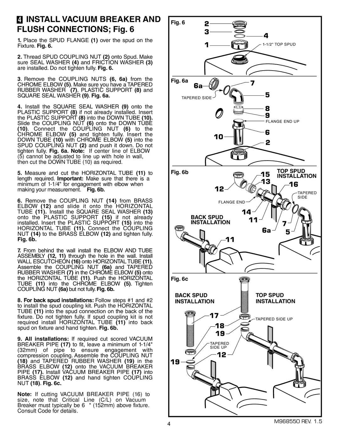
1.Place the SPUD FLANGE (1) over the spud on the Fixture. Fig. 6.
2.Thread SPUD COUPLING NUT (2) onto Spud. Make sure SEAL WASHER (4) and FRICTION WASHER (3) are installed. Do not tighten fully. Fig. 6.
3. Remove the COUPLING NUTS (6, 6a) from the CHROME ELBOW (5). Make sure you have a TAPERED RUBBER WASHER (7), PLASTIC SUPPORT (8) and SQUARE SEAL WASHER (9). Fig. 6a.
4.Install the SQUARE SEAL WASHER (9) onto the PLASTIC SUPPORT (8) if not already installed. Insert the PLASTIC SUPPORT (8) into the DOWN TUBE (10). Slide the COUPLING NUT (6) onto the DOWN TUBE (10). Connect the COUPLING NUT (6) to the CHROME ELBOW (5) and tighten fully. Insert the DOWN TUBE (10) with CHROME ELBOW (5) into the SPUD COUPLING NUT (2) and push it down. Do not tighten fully. Fig. 6a. Note: If center line of ELBOW
(5) cannot be adjusted to line up with hole in wall, then cut the DOWN TUBE (10) as required.
5.Measure and cut the HORIZONTAL TUBE (11) to length required. Important: Make sure that there is a minimum of
6.Remove the COUPLING NUT (14) from BRASS ELBOW (12) and slide it onto the HORIZONTAL TUBE (11). Install the SQUARE SEAL WASHER (13) onto the PLASTIC SUPPORT (15) if not already installed. Insert the PLASTIC SUPPORT (15) into the HORIZONTAL TUBE (11). Connect the COUPLING NUT (14) to the BRASS ELBOW (12) and tighten fully.
Fig. 6b.
7.From behind the wall install the ELBOW AND TUBE ASSEMBLY (12, 11) through the hole in the wall. Install WALL ESCUTCHEON (16) onto HORIZONTAL TUBE (11). Assemble the COUPLING NUT (6a) and TAPERED RUBBER WASHER (7) in the CHROME ELBOW (5) onto the HORIZONTAL TUBE (11). Push the HORIZONTAL TUBE (11) into the CHROME ELBOW (5). Tighten COUPLING NUT (6a) but not fully. Fig. 6b.
8.For back spud installations: Follow steps #1 and #2 to install the spud coupling kit. Push the HORIZONTAL TUBE (11) into the spud connection on the back of the fixture. Do not tighten fully. If spud coupling kit is not required install HORIZONTAL TUBE (11) into back spud on fixture and hand tighten. Fig. 6b.
9.All installations: If required cut scored VACUUM BREAKER PIPE (17) to fit, leave a minimum of
Note: If cutting VACUUM BREAKER PIPE (16) to size, note that Critical Line (C/L) on Vacuum Breaker must typically be 6" (152mm) above fixture.
Consult Code for details.
Fig. 6 | 2 |
|
|
| 3 | 4 |
|
|
|
| |
| 1 | ||
|
|
| |
Fig. 6a | 6a | 7 |
|
|
|
| |
TAPERED SIDE | 5 |
| |
|
| ||
|
| 8 |
|
|
| 9 |
|
|
| FLANGE END UP | |
| 10 | 6 |
|
| 2 |
| |
|
|
| |
Fig. 6b |
| 15 | TOP SPUD |
|
| INSTALLATION | |
| 12 | 13 | 16 |
|
| ||
|
| TAPERED | |
|
|
| |
|
|
| SIDE |
| FLANGE END |
| |
| BACK SPUD | 14 |
|
| 11 |
| |
| INSTALLATION | 7 | |
| 6a | ||
| 11 | 5 | |
|
|
| |
Fig. 6c |
|
|
|
BACK SPUD | TOP SPUD | ||
INSTALLATION | INSTALLATION | ||
| 17 | TAPERED SIDE UP | |
|
| ||
| 18 |
|
|
| 19 |
|
|
| TAPERED |
|
|
| SIDE UP |
|
|
19 | 12 |
|
|
|
|
| |
4 |
|
| M968550 REV. 1.5 |
|
|
| |