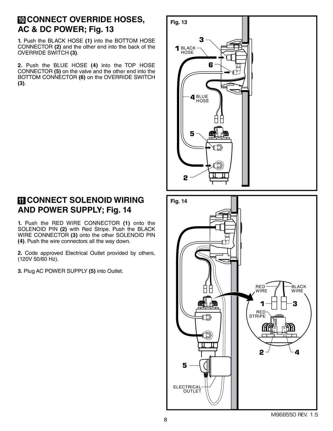
10 CONNECT OVERRIDE HOSES, AC & DC POWER; Fig. 13
1.Push the BLACK HOSE (1) into the BOTTOM HOSE CONNECTOR (2) and the other end into the back of the OVERRIDE SWITCH (3).
2.Push the BLUE HOSE (4) into the TOP HOSE CONNECTOR (5) on the valve and the other end into the BOTTOM CONNECTOR (6) on the OVERRIDE SWITCH
(3).
Fig. 13
1 BLACKHOSE
3 |
6 |
11CONNECT SOLENOID WIRING AND POWER SUPPLY; Fig. 14
1.Push the RED WIRE CONNECTOR (1) onto the SOLENOID PIN (2) with Red Stripe. Push the BLACK WIRE CONNECTOR (3) onto the other SOLENOID PIN
(4). Push the wire connectors all the way down.
2.Code approved Electrical Outlet provided by others, (120V 50/60 Hz).
3.Plug AC POWER SUPPLY (5) into Outlet.
4 BLUEHOSE
5
![]()
![]()
![]()
![]()
![]()
2 ![]()
![]()
![]()
Fig. 14
RED | BLACK |
WIRE | WIRE |
1 ![]()
![]()
![]() 3
3
RED
STRIPE
2 4
5
ELECTRICAL
OUTLET
M968550 REV. 1.5
8
