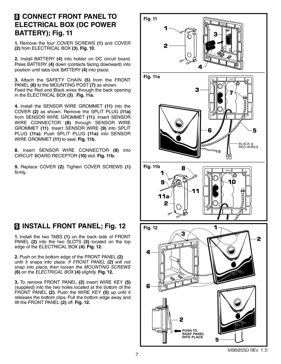
8CONNECT FRONT PANEL TO ELECTRICAL BOX (DC POWER BATTERY); Fig. 11
1.Remove the four COVER SCREWS (1) and COVER
(2) from ELECTRICAL BOX (3). Fig. 10.
2.Install BATTERY (4) into holder on DC circuit board. Press BATTERY (4) down (contacts facing downward) into position until tabs lock BATTERY (4) into place.
3.Attach the SAFETY CHAIN (5) from the FRONT PANEL (6) to the MOUNTING POST (7) as shown.
Feed the Red and Black wires through the back opening in the ELECTRICAL BOX (3). Fig. 11a.
4.Install the SENSOR WIRE GROMMET (11) into the COVER (2) as shown. Remove the SPLIT PLUG (11a) from SENSOR WIRE GROMMET (11). Insert SENSOR WIRE CONNECTOR (8) through SENSOR WIRE GROMMET (11). Insert SENSOR WIRE (9) into SPLIT PLUG (11a). Push SPLIT PLUG (11a) into SENSOR WIRE GROMMET (11) to seal. Fig. 11b.
8.Insert SENSOR WIRE CONNECTOR (8) into CIRCUIT BOARD RECEPTOR (10) slot. Fig. 11b.
9.Replace COVER (2). Tighten COVER SCREWS (1) firmly.
9INSTALL FRONT PANEL; Fig. 12
1.Install the two TABS (1) on the back side of FRONT PANEL (2) into the two SLOTS (3) located on the top edge of the ELECTRICAL BOX (4). Fig. 12.
2.Push on the bottom edge of the FRONT PANEL (2) until it snaps into place. If FRONT PANEL (2) will not snap into place, then loosen the MOUNTING SCREWS
(6) on the ELECTRICAL BOX (4) slightly. Fig. 12.
3.To remove FRONT PANEL (2) insert WIRE KEY (5) (supplied) into the two holes located at the bottom of the FRONT PANEL (2). Push the WIRE KEY (5) up until it releases the bottom clips. Pull the bottom edge away and lift the FRONT PANEL (2) off. Fig. 12.
Fig. 11 |
|
|
|
1 |
|
| T O P |
|
| 3 | |
|
|
| |
2 |
|
|
|
|
| 4 |
|
Fig. 11a |
|
| T O P |
|
|
| |
|
| 3 | 7 |
|
|
| |
|
| 6 | 5 |
|
|
| BLACK & |
|
|
| RED WIRES |
Fig. 11b |
| 8 | T O P |
1 |
|
|
|
9 |
|
| 10 |
11a |
| 11 |
|
|
|
| |
2 |
|
|
|
Fig. 12 |
| 3 | 1 |
|
| 2 | |
|
|
| |
| T O | P |
|
|
|
| |
4 |
|
|
|
6 |
|
|
|
| 2 |
| |
PUSH TO
SNAP PANEL
INTO PLACE
7
5
M968550 REV. 1.5