13 HOWTO INSTALL NEW BATTERY; |
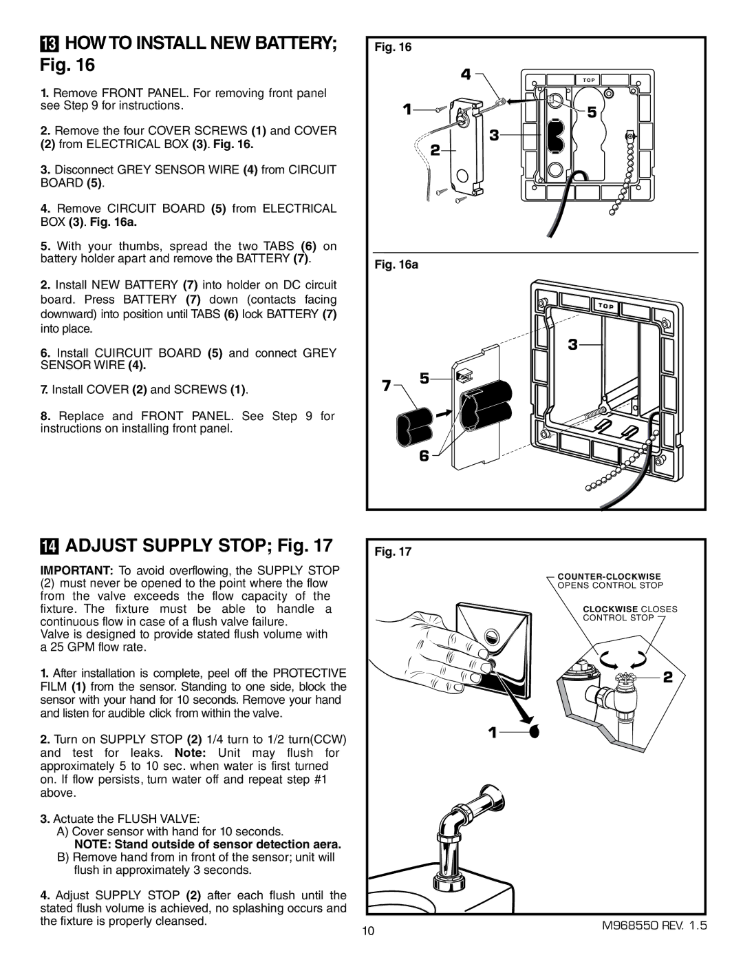
Fig. 16 |
1. Remove FRONT PANEL. For removing front panel |
see Step 9 for instructions. |
2. Remove the four COVER SCREWS (1) and COVER |
(2) from ELECTRICAL BOX (3). Fig. 16. |
3. Disconnect GREY SENSOR WIRE (4) from CIRCUIT |
BOARD (5). |
4. Remove CIRCUIT BOARD (5) from ELECTRICAL |
BOX (3). Fig. 16a. |
5. With your thumbs, spread the two TABS (6) on |
battery holder apart and remove the BATTERY (7). |
Fig. 16
4 ![]()
1![]()
![]()
![]()
![]()
![]()
![]()
![]()
![]()
![]()
![]()
![]()
![]()
3
2
T O P
5 |
2.Install NEW BATTERY (7) into holder on DC circuit board. Press BATTERY (7) down (contacts facing downward) into position until TABS (6) lock BATTERY (7) into place.
6.Install CUIRCUIT BOARD (5) and connect GREY SENSOR WIRE (4).
7.Install COVER (2) and SCREWS (1).
8.Replace and FRONT PANEL. See Step 9 for instructions on installing front panel.
Fig. 16a
3
7 | 5 |
|
6![]()
14ADJUST SUPPLY STOP; Fig. 17
IMPORTANT: To avoid overflowing, the SUPPLY STOP
(2)must never be opened to the point where the flow from the valve exceeds the flow capacity of the fixture. The fixture must be able to handle a continuous flow in case of a flush valve failure.
Valve is designed to provide stated flush volume with a 25 GPM flow rate.
1.After installation is complete, peel off the PROTECTIVE FILM (1) from the sensor. Standing to one side, block the sensor with your hand for 10 seconds. Remove your hand and listen for audible“click” from within the valve.
2.Turn on SUPPLY STOP (2) 1/4 turn to 1/2 turn(CCW) and test for leaks. Note: Unit may flush for approximately 5 to 10 sec. when water is first turned on. If flow persists, turn water off and repeat step #1 above.
3.Actuate the FLUSH VALVE:
A)Cover sensor with hand for 10 seconds.
NOTE: Stand outside of sensor detection aera.
B)Remove hand from in front of the sensor; unit will flush in approximately 3 seconds.
4.Adjust SUPPLY STOP (2) after each flush until the stated flush volume is achieved, no splashing occurs and the fixture is properly cleansed.
Fig. 17
OPENS CONTROL STOP
CLOCKWISE CLOSES
CONTROL STOP
2
1
10 | M968550 REV. 1.5 |
|