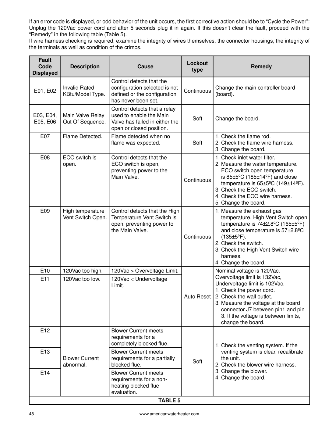
If an error code is displayed, or odd behavior of the unit occurs, the first corrective action should be to “Cycle the Power”: Unplug the 120Vac power cord and after 5 seconds plug it in again. If this doesn’t clear the fault, proceed with the “Remedy” in the following table (Table 5).
If wire harness checking is required, examine the integrity of wires themselves, the connector housings, the integrity of the terminals as well as condition of the crimps.
Fault |
|
| Lockout |
| |
Code | Description | Cause | Remedy | ||
type | |||||
Displayed |
|
|
| ||
|
|
|
| ||
|
| Control detects that the |
|
| |
E01, E02 | Invalid Rated | configuration selected is not | Continuous | Change the main controller board | |
KBtu/Model Type. | defined or the configuration | (board). | |||
|
| has never been set. |
|
| |
|
| Control detects that a relay |
|
| |
E03, E04, | Main Valve Relay | used to enable the Main | Soft | Change the board. | |
E05, E06 | Out Of Sequence. | Valve has failed in either the | |||
|
| ||||
|
| open or closed position. |
|
| |
E07 | Flame Detected. | Flame detected when no |
| 1. Check the flame rod. | |
|
| flame was expected. | Soft | 2. Check the flame wire harness. | |
|
|
|
| 3. Change the board. | |
E08 | ECO switch is | Control detects that the |
| 1. Check inlet water filter. | |
| open. | ECO switch is open, |
| 2. Measure the water temperature. | |
|
| preventing power to the |
| ECO switch open temperature | |
|
| Main Valve. | Continuous | is 85±5ºC (185±14ºF) and close | |
|
|
| temperature is 65±5ºC (149±14ºF). | ||
|
|
|
| ||
|
|
|
| 3. Check the ECO switch. | |
|
|
|
| 4. Check the ECO wire harness. | |
|
|
|
| 5. Change the board. | |
E09 | High temperature | Control detects that the High |
| 1. Measure the exhaust gas | |
| Vent Switch Open. | Temperature Vent Switch is |
| temperature. High Vent Switch open | |
|
| open, preventing power to |
| temperature is 74±2.8ºC (165±5ºF) | |
|
| the Main Valve. |
| and close temperature is 57±2.8ºC | |
|
|
| Continuous | (135±5ºF). | |
|
|
|
| 2. Check the switch. | |
|
|
|
| 3. Check the High Vent Switch wire | |
|
|
|
| harness. | |
|
|
|
| 4. Change the board. | |
E10 | 120Vac too high. | 120Vac > Overvoltage Limit. |
| Nominal voltage is 120Vac. | |
E11 | 120Vac too low. | 120Vac < Undervoltage |
| Overvoltage limit is 132Vac, | |
|
| Limit. |
| Undervoltage limit is 102Vac. | |
|
|
|
| 1. Check the power cord. | |
|
|
| Auto Reset | 2. Check the wall outlet. | |
|
|
|
| 3. Measure the voltage at the board | |
|
|
|
| connector J7 between pin1 and pin | |
|
|
|
| 3. If the voltage is between limits, | |
|
|
|
| change the board. | |
E12 |
| Blower Current meets |
|
| |
|
| requirements for a |
|
| |
|
| completely blocked flue. |
| 1. Check the venting system. If the | |
E13 |
| Blower Current meets |
| venting system is clear, recalibrate | |
| Blower Current | requirements for a partially | Soft | the unit. | |
| abnormal. | blocked flue. | 2. Check the blower wire harness. | ||
|
| ||||
|
|
|
| 3. Change the blower. | |
E14 |
| Blower Current meets |
| ||
|
| requirements for a non- |
| 4. Change the board. | |
|
| heating blocked flue |
|
| |
|
| evaluation. |
|
| |
|
| TABLE 5 |
|
|
48 | www.americanwaterheater.com |
