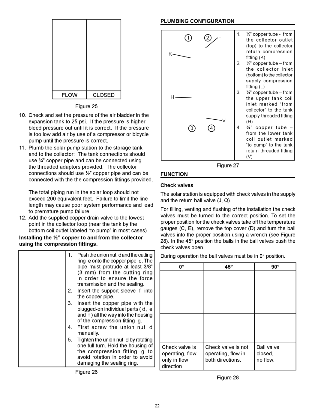
PLUMBING CONFIGURATION

FLOW

CLOSED

Figure 25

10.

Check and set the pressure of the air bladder in the


expansion tank to 25 psi. If the pressure is higher


bleed pressure out until it is correct. If the pressure


is too low add air by use of a compressor or bicycle


pump until the pressure is correct.

11.

Plumb the solar pump station to the storage tank


and to the collector: The tank connections should


use ¾” copper pipe and can be connected using

1

2

L

K

H

V

3 4

1.½” copper tube - from the collector outlet (top) to the collector return compression fitting (K)

2.½” copper tube – from the collector inlet (bottom) to the collector supply compression fitting (L)

3.¾” copper tube – from the upper tank coil inlet marked “from collector” to the tank supply threaded fitting

(H)

4.¾” copper tube – from the lower tank coil outlet marked “to pump” to the tank return threaded fitting

(V)

the threaded adaptors provided. The collector

connections should use ½” copper pipe and can be

connected with the the compression fittings provided.

The total piping run in the solar loop should not

exceed 200 equivalent feet. Failure to limit the line

length may cause poor system performance and lead

to premature pump failure.

12. Add the supplied copper drain valve to the lowest

point in the collector loop (near the tank by the

bottom coil outlet labeled “to pump” in most cases)

Installing the ½” copper to and from the collector using the compression fittings.

1.Pushtheunionnutdandthecutting ring eonto the copper pipe c. The pipe must protrude at least 3/8” (3 mm) from the cutting ring in order to ensure the force transmission and the sealing.

2.Insert the support sleeve f into the copper pipe.

3.Insert the copper pipe with the plugged-on individual parts (d, e and f) all the way into the housing of the compression fitting g.

4.First screw the union nut d manually.

5.Tighten the union nut dby rotating one full turn. Hold the housing of the compression fitting g to avoid rotation in order to avoid damaging the sealing ring.

Figure 26

Figure 27

FUNCTION

Check valves

The solar station is equipped with check valves in the supply and the return ball valve (J, Q).

For filling, venting and flushing of the installation the check valves must be turned to the correct position. To set the proper position for the check valves take off the temperature gauges (C, E), remove the top cover (D) and turn the ball valves into the proper position using a wrench (see Figure 28). In the 45° position the balls in the ball valves push the check valves open.

During operation the ball valves must be in 0° position.

45°

90°


Check valve is

Check valve is not

Ball valve

operating, flow

operating, flow in

closed,

only in flow

both directions.

no flow.

direction


Figure 28


22

Page 22
Image 22
American Water Heater 318281-000 instruction manual Plumbing Configuration, Function, Check valves

318281-000 specifications

The American Water Heater 318281-000 is a highly regarded product in the realm of residential water heating, providing a perfect blend of efficiency, reliability, and advanced technology. Designed to deliver hot water conveniently and effectively, this model is suitable for various home sizes and needs.

One of the standout features of the 318281-000 is its energy efficiency. This water heater is built to comply with stringent energy regulations, helping households reduce their utility costs without compromising on performance. It typically features a high Energy Factor (EF) rating, indicating more efficient energy use for heating water. This technology not only helps in saving on energy bills but also contributes to environmental sustainability by reducing the carbon footprint of the home.

The 318281-000 employs advanced insulation techniques that minimize heat loss, ensuring that hot water is readily available whenever needed. Its design often includes a high-quality tank with foam insulation, providing better retention of heat and, consequently, more hot water availability.

Moreover, the water heater showcases a robust build quality, often incorporating a glass-lined tank for enhanced durability and protection against corrosion. This feature extends the life of the unit and reduces the need for frequent maintenance. In addition, a sacrificial anode rod is typically included to further prevent rust and enhance tank longevity.

The installation of the American Water Heater 318281-000 is designed to be user-friendly, with flexible venting options and straightforward plumbing requirements. Many models come ready for either natural gas or propane configurations, providing homeowners with choices that suit their specific needs.

Another appealing aspect of this water heater is the availability of modern safety features. It generally includes a pressure relief valve and a temperature dial, making it easier for users to manage and maintain safe operation levels.

In conclusion, the American Water Heater 318281-000 stands out in the crowded water heating market by marrying high efficiency, advanced technology, and user-centered design. Its ability to provide a consistent hot water supply while being environmentally friendly makes it an attractive option for homes looking to upgrade or replace their existing water heating systems. With its blend of durability and smart features, this model is indeed a wise investment for those seeking longevity and efficiency in their home hot water solutions.