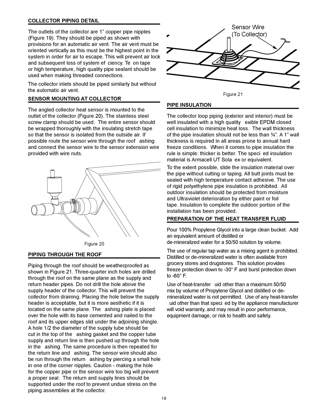
318281-000 specifications
The American Water Heater 318281-000 is a highly regarded product in the realm of residential water heating, providing a perfect blend of efficiency, reliability, and advanced technology. Designed to deliver hot water conveniently and effectively, this model is suitable for various home sizes and needs.One of the standout features of the 318281-000 is its energy efficiency. This water heater is built to comply with stringent energy regulations, helping households reduce their utility costs without compromising on performance. It typically features a high Energy Factor (EF) rating, indicating more efficient energy use for heating water. This technology not only helps in saving on energy bills but also contributes to environmental sustainability by reducing the carbon footprint of the home.
The 318281-000 employs advanced insulation techniques that minimize heat loss, ensuring that hot water is readily available whenever needed. Its design often includes a high-quality tank with foam insulation, providing better retention of heat and, consequently, more hot water availability.
Moreover, the water heater showcases a robust build quality, often incorporating a glass-lined tank for enhanced durability and protection against corrosion. This feature extends the life of the unit and reduces the need for frequent maintenance. In addition, a sacrificial anode rod is typically included to further prevent rust and enhance tank longevity.
The installation of the American Water Heater 318281-000 is designed to be user-friendly, with flexible venting options and straightforward plumbing requirements. Many models come ready for either natural gas or propane configurations, providing homeowners with choices that suit their specific needs.
Another appealing aspect of this water heater is the availability of modern safety features. It generally includes a pressure relief valve and a temperature dial, making it easier for users to manage and maintain safe operation levels.
In conclusion, the American Water Heater 318281-000 stands out in the crowded water heating market by marrying high efficiency, advanced technology, and user-centered design. Its ability to provide a consistent hot water supply while being environmentally friendly makes it an attractive option for homes looking to upgrade or replace their existing water heating systems. With its blend of durability and smart features, this model is indeed a wise investment for those seeking longevity and efficiency in their home hot water solutions.

