AD9843A

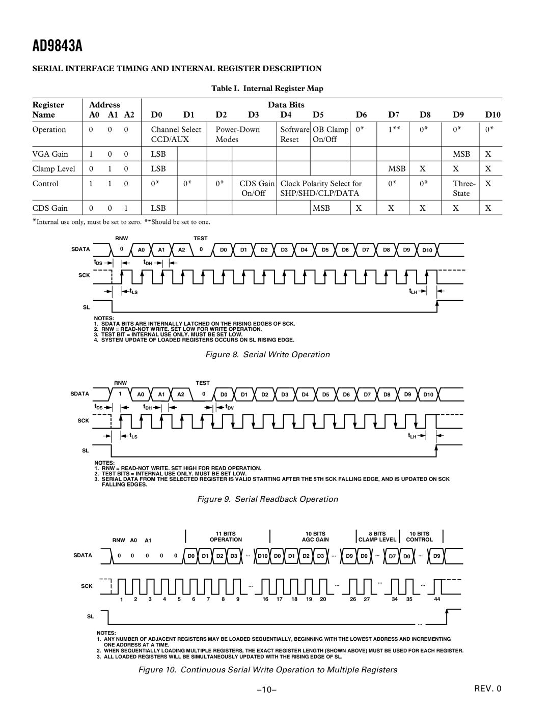
SERIAL INTERFACE TIMING AND INTERNAL REGISTER DESCRIPTION

Table I. Internal Register Map

Register

Address


Data Bits


Name

A0

A1

A2

D0

D1

D2

D3

D4

D5

D6

D7

D8

D9

D10


Operation

0

0

0

Channel Select

Power-Down

Software

OB Clamp

0*

1**

0*

0*

0*


CCD/AUX

Modes


Reset

On/Off


VGA Gain

1

0

0

LSB


MSB

X


Clamp Level

0

1

0

LSB


MSB

X

X

X


Control

1

1

0

0*

0*

0*


CDS Gain

Clock Polarity Select for

0*

0*

Three-

X


On/Off

SHP/SHD/CLP/DATA


State


CDS Gain

0

0

1

LSB


MSB

X

X

X

X

X


*Internal use only, must be set to zero. **Should be set to one.

SDATA

tDS

SCK

RNW


TEST


0

A0

A1

A2

0

D0

D1

D2

D3

D4

D5

D6

D7

D8

D9

D10


tDH


tLS


tLH


SL

NOTES:

1.SDATA BITS ARE INTERNALLY LATCHED ON THE RISING EDGES OF SCK.

2.RNW = READ-NOT WRITE. SET LOW FOR WRITE OPERATION.

3.TEST BIT = INTERNAL USE ONLY. MUST BE SET LOW.

4.SYSTEM UPDATE OF LOADED REGISTERS OCCURS ON SL RISING EDGE.

Figure 8. Serial Write Operation


RNW


SDATA

1


A0

A1


tDS


tDH


SCK

tLS

SL

TEST

A2

0

D0

D1

D2

D3

D4

D5

D6

D7

D8

D9

D10

tDV

tLH

NOTES:

1.RNW = READ-NOT WRITE. SET HIGH FOR READ OPERATION.

2.TEST BITS = INTERNAL USE ONLY. MUST BE SET LOW.

3.SERIAL DATA FROM THE SELECTED REGISTER IS VALID STARTING AFTER THE 5TH SCK FALLING EDGE, AND IS UPDATED ON SCK FALLING EDGES.

Figure 9. Serial Readback Operation


11 BITS

10 BITS

8 BITS

10 BITS


RNW

A0

A1

OPERATION

AGC GAIN

CLAMP LEVEL

CONTROL

SDATA

0

0

0 0

0 D0 D1 D2 D3

... D10 D0 D1 D2 D3 ...

D9 D0 ... D7

D0 ... D9

SCK

SL

......

1

2

3

4

5

6

7

8

9

16

17

18

19

20

26

27

...

...

34

35

44

...

NOTES:

1.ANY NUMBER OF ADJACENT REGISTERS MAY BE LOADED SEQUENTIALLY, BEGINNING WITH THE LOWEST ADDRESS AND INCREMENTING ONE ADDRESS AT A TIME.

2.WHEN SEQUENTIALLY LOADING MULTIPLE REGISTERS, THE EXACT REGISTER LENGTH (SHOWN ABOVE) MUST BE USED FOR EACH REGISTER.

3.ALL LOADED REGISTERS WILL BE SIMULTANEOUSLY UPDATED WITH THE RISING EDGE OF SL.

Figure 10. Continuous Serial Write Operation to Multiple Registers

–10–

REV. 0

Page 10
Image 10
Analog Devices AD9843A Register Address Data Bits Name D10, Serial Interface Timing and Internal Register Description

AD9843A specifications

The Analog Devices AD9843A is a high-performance, integrated analog-to-digital converter (ADC) designed for a variety of applications requiring precise signal conversion. This device boasts a 12-bit resolution, making it suitable for capturing fine details in complex signals. The AD9843A operates with a maximum sampling rate of up to 130 MSPS (mega samples per second), which allows it to handle fast-changing waveforms effectively, ideal for applications in the fields of telecommunications, instrumentation, and medical imaging.

One of the standout features of the AD9843A is its dual-channel architecture, which enables simultaneous sampling of two input signals. This capability is particularly beneficial in applications such as radar and sonar systems, where capturing multiple input sources in parallel is critical. Furthermore, the ADC incorporates a high-speed programmable gain amplifier (PGA), providing adjustable gain settings to accommodate a wide range of signal amplitudes, ensuring optimal performance across various input conditions.

The AD9843A employs Differential Non-Linearity (DNL) and Integral Non-Linearity (INL) specifications, both of which contribute to its impressive accuracy and linearity. With a DNL of ±0.5 LSB (least significant bit) and an INL of ±1 LSB, the AD9843A minimizes distortion and enhances the fidelity of the digital representation of analog signals. Additionally, the device features low noise performance, which is essential for obtaining high-quality signal digitization, especially in sensitive applications where signal integrity is paramount.

Another key characteristic is the integrated sample-and-hold circuit that allows the ADC to capture input signals with minimal distortion during the conversion process. This design choice helps to stabilize the input signal, reducing the effect of sampling jitter. The AD9843A also provides various output data formats, including binary, gray code, and two's complement, which gives designers the flexibility to interface the ADC with different digital systems.

In terms of power consumption, the AD9843A is efficient, operating at a typical supply voltage of 5V. It offers a significant advantage for battery-operated devices by ensuring that the power requirements are kept low without compromising performance. With its combination of high throughput, low noise, and versatility, the Analog Devices AD9843A stands out as a robust solution for high-speed data acquisition systems, making it a preferred choice among engineers and designers across various industries.